Assembly Instructions – Full-Jet Valve VMS-02
Walther Systemtechnik GmbH – D 76726 Germersheim
Telefon: +49 (0)7274-7022-0 Telefax: +49 (0)7274-7022-91
http://www.walther-2000.de – info@walther-2000.de
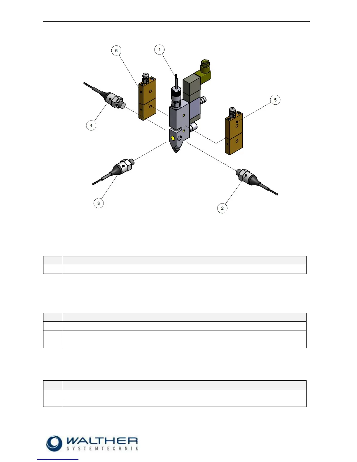
10.4.2 Add-on Elements
Needle Sensor
The installation of a sensor for the raster needle is factory-made. It is integrated in the raster needle lock
(pos. 7.0 of spare parts list). As a spare part, the raster needle lock is always delivered as a complete unit,
since the initiator is factory-adjusted and pasted in.
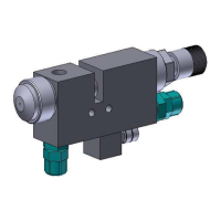
Pressure sensor
The attachment of a pressure sensor is also factory-made. Its position can optionally be on the side (left /
right) or on top. For additional information please refer to the Operating Manual “Pressure Sensors 97PA-
21x-xxx“.
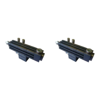
Pressure sensor mounted on the left of the pulse valve
Pressure sensor mounted on top of the pulse valve
Pressure sensor mounted on the right side of the pulse valve
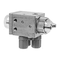
Hotplate
The installation of a heating plate is also factory-made. Its position can optionally be on the left or on the right
side. For further information please refer to the Description “Heating and Accessories.
Hotplate mounted on the left side of the pulse valve
Hotplate mounted on the right side of the pulse valve