WARN® INDUSTRIES PAGE 20 72171 Rev A0
Check to see if the bottom edge of the support
receiver is now higher than the bottom plow
mount surface. If so, follow the steps in the
section above.
• If the arms and arm stops are in position #2, and
the bottom edge of the receiver is still lower than
the bottom surface of the plow mount, then
remove the arm stops and switch the arm settings
from position #2 to position #3 as described
earlier in this document. Check to see if the
bottom edge of the support receiver is now higher
than the bottom plow mount surface. If so, follow
the steps in the section above.
• If the arms are in position #3, and the bottom
edge of the support receiver is still lower than the
bottom surface of the plow mount, then lower the
shock settings on the vehicle until the desire
height is reached.
6. Once the receivers are aligned, get back in the
vehicle and slowly drive the vehicle into plow
support until the support fully engages into the
plow mount.
7. Turn off the vehicle, set the parking brake, and
walk over to the plow support. Check to make
sure that the plow support receivers are fully
engaged in the plow mount. You may have to
push on the plow support or pull on the plow to
get the receiver to go in as far as possible.
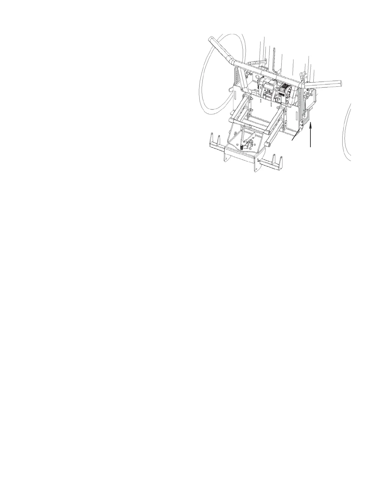
8. Pull the detent pin out in one of the legs, firmly
slide and lift the stand until it locks fully into the
plow mount, place the detent pin back into the
bottom hole in the plow support. See Figure 40.
Repeat on the other side.
9. Double check that the plow is fully engaged into
the system. Pull and push on the plow blade to
ensure nothing on the plow mount or plow support
moves. The blade should be solidly attached to
the vehicle.
10. The calibration of the plow is now complete.
Calibrate the plow every time new tires are added
to the vehicle, the shock settings are changed, or
weight is added/removed from the vehicle.
Perform calibration at least once a season even if
nothing has changed on the vehicle.
Figure 40 Lock latch into plow mount, install detent pins
Add detent pin
to bottom hole
(blade not shown)