WARN INDUSTRIES PAGE 13 84855A2
V. TRX420 Specic Wiring
Instructions
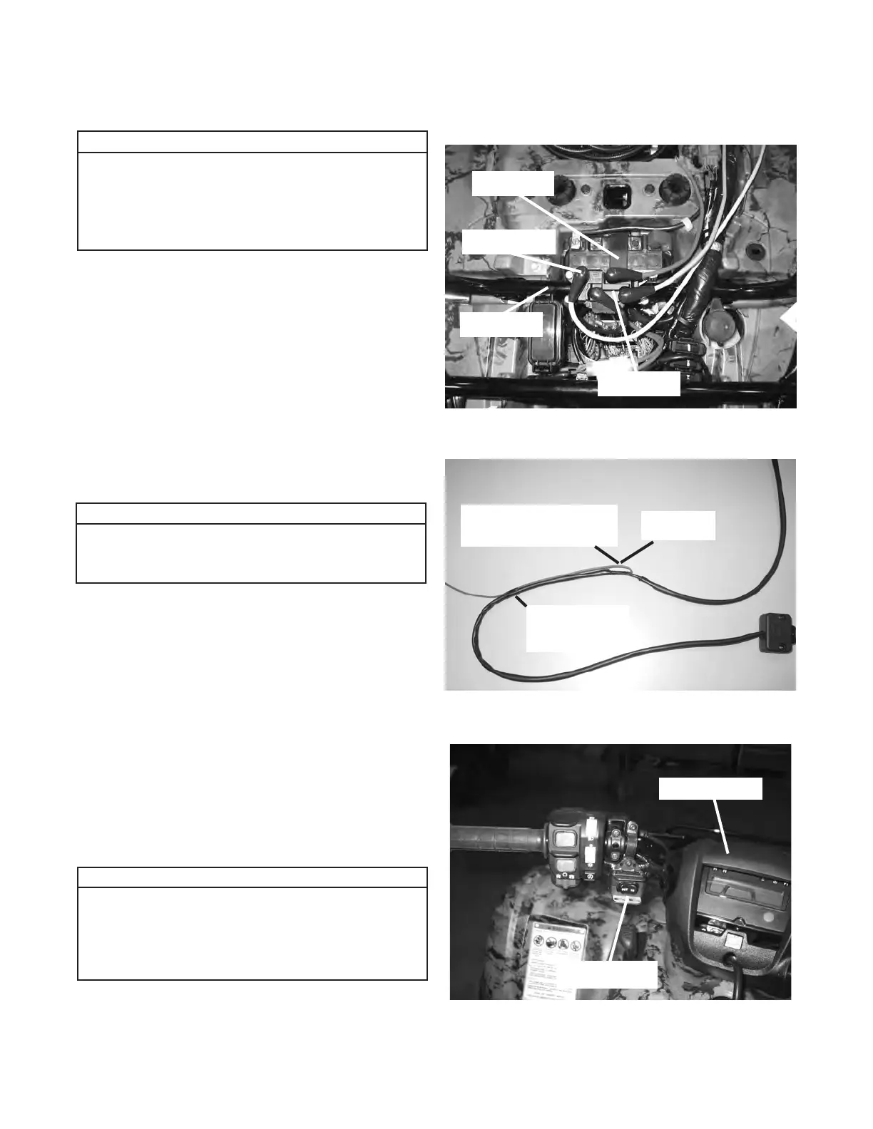
1. Contactor Location - Step Four in the Installation
and Specication Guide:
a. The contactor is located under the panel behind the
seat, gure 26.
b. Remove the seat and the plastic panel covering the
battery.
c. Position the contactor with the yellow and red
terminals closest to the battery, gure 26. Fasten
the contactor to the frame tube using the supplied
1/4-20 x 1” x 1 3/4” u-bolts, 1/4” at washers, and
1/4-20 lock nuts. Do not tighten at this time.
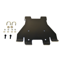
2. Handlebar Switch Installation - Step Three in the
Installation and Specication Guide:
a. Before installing the winch switch, route the red wire
towards the switch case. Secure with electrical tape
a distance of approximately 25cm (10in) from where
the red wire protrudes from the back casing towards
the switch case, gure 27. This will allow you to see
the red wire when routing the switch wires, down the
steering column, to the contactor.
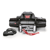
b. Mount the winch switch in the location shown in
gure 28. The recommended location is on the
bottom of the left side of the handlebars.
It should be noted that the following instructions
are ATV specic only. The following instructions
should be referred to as reference instructions to
assist wiring the winch from the Installation and
Specication Guide supplied in the winch kit.
Notice
Figure 26 Contactor Location
Battery
Frame Tube
Contactor
Yellow Terminal
Notice
Please note that all wires in the wiring photo-
graphs are shown without conduit on the colored
wires. This is for clarity in the instructions.
Please refer to the Installation and Specication
Guide, supplied in the winch kit, for specic
details on how to install the switch onto the ATV.
Please note that the switch extension brackets
are not used in the TRX420 application.
Notice
Figure 27 Red Wire - Tie-off 25cm (10in)
Red Wire
Secure a distance of 25cm
(10in) from this point
Secure with
Electrical Tape
Figure 28 Handlebar Switch Location
Switch Location
Handlebar Cowl