WARN INDUSTRIES PAGE 14 84855A2
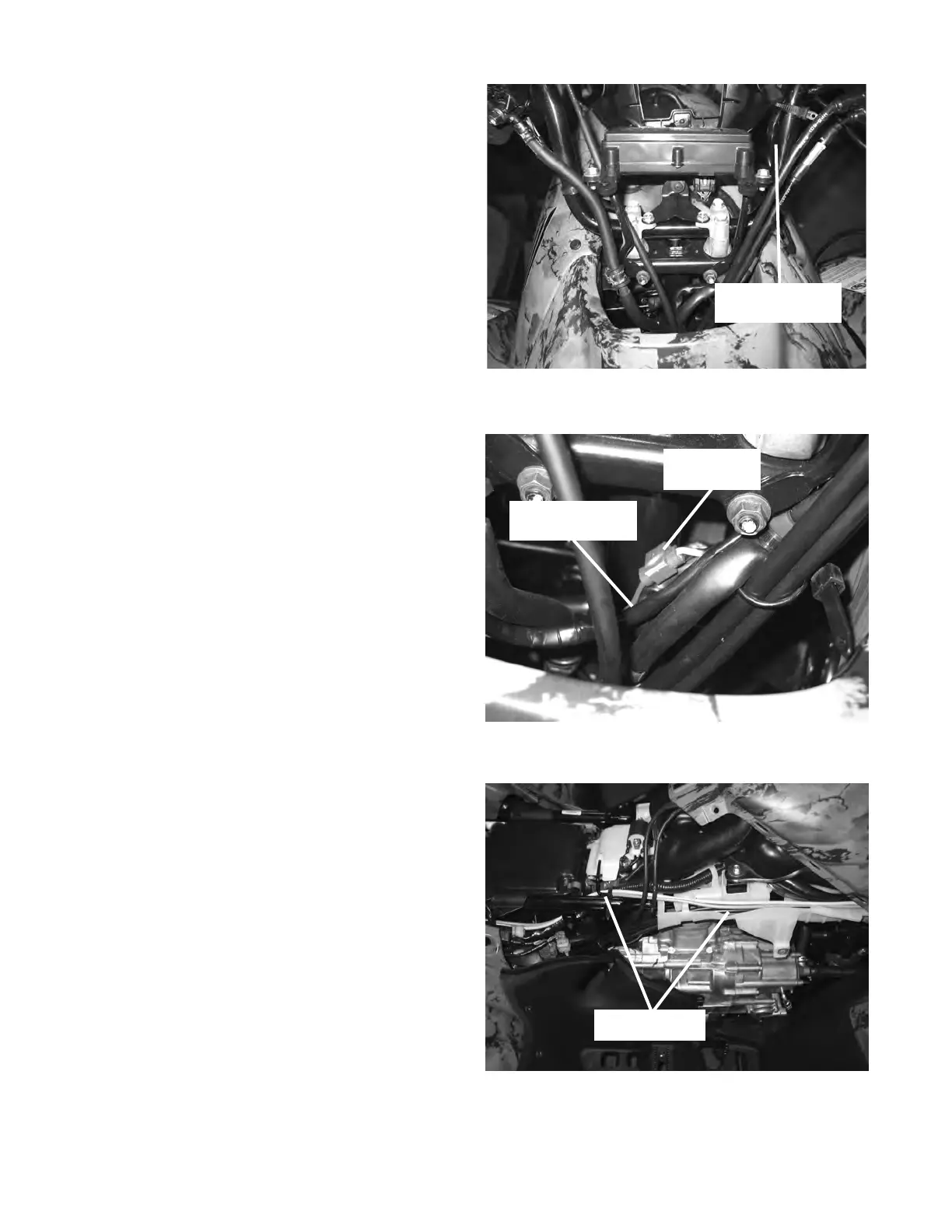
Figure 30 Connecting Switch - Red Wire
Figure 31 Switch Lead Routing
Existing Harness
Figure 29 Handlebar Switch Wire Routing
Handlebar Switch
Routing
Ignition Switch Wire Har-
ness
Scotch Lock
Splice
c. Remove the handlebar cowl to expose the ignition
switch wire harness, refer to the Honda service
manual for model specic instructions. Route the
handlebar winch switch wire down the handle bar,
gure 29. Use existing and supplied plastic tie
straps to secure handlebar switch leads.
d. Locate the ignition switch wire harness in front of the
steering column, gure 30. Cut back the harness
protective cover and splice the red switch wire, using
the scotch lock supplied in the mounting kit, into the
pink wire located in the ignition switch wire harness.
Before making the splice, make sure that the pink
wire only has power when the key switch is on.
Trim the red switch wire excess approximately 20cm
(8 in). Retape with electrical tape.
e. Reinstall the handlebar cowl. Use the original
hardware to reattach the handlebar cowl. Tighten
the bolts securely.
f. Remove the right side panels by removing the
fasteners holding them in place. Keep the fasteners
for reinstallation.
g. Route switch leads to the contactor at the rear of the
ATV by following the original wiring harnesses along
the right side of the frame, gure 31.