987606A1.doc Page 17 of 46
2.4.2 ASSEMBLY OF MOTOR
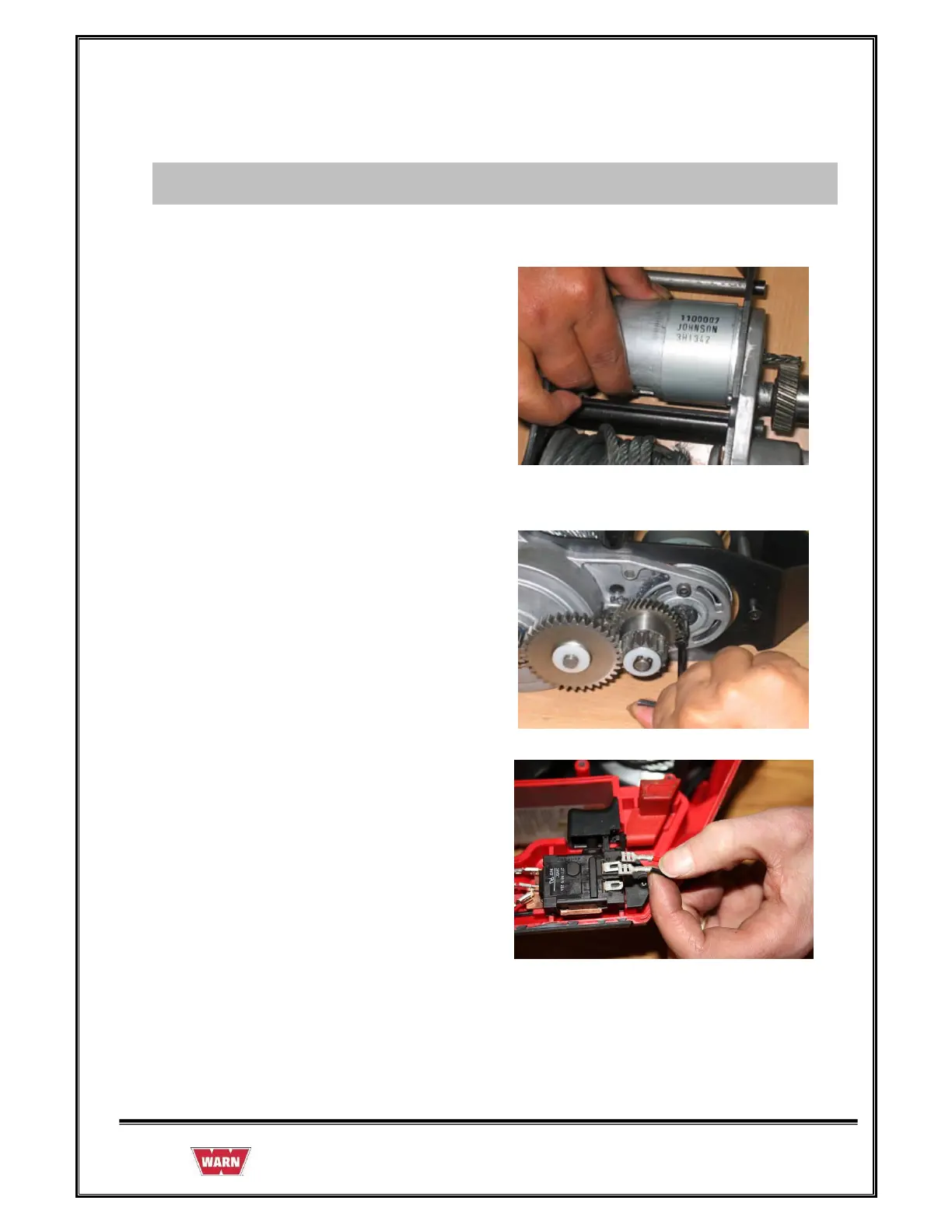
8. Install the Motor assembly in to the
Chassis assembly.
9. Tighten the two CapScrews to secure
Motor assembly in position.
10. Install Motor leads to top terminals of
Switch per wiring diagram (Red to M+ or
M1, Black to M- or M2).