987606A1.doc Page 41 of 46
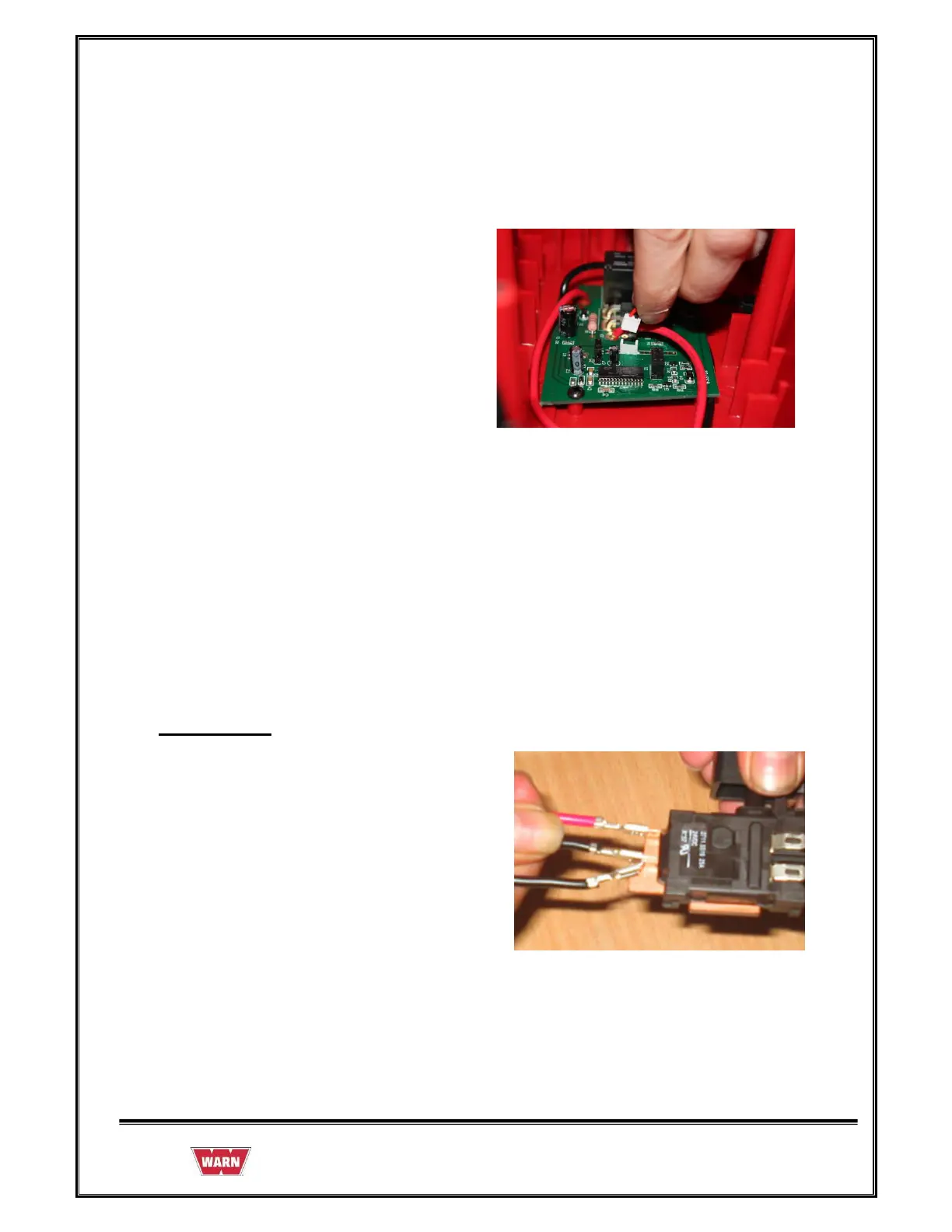
5. Route Red Lead Wire (soldered to Male
Terminal Support) from J2 Terminal on
Circuit Board through wire guides up to
rear of Housing to where the Male
Terminal support is mounted.
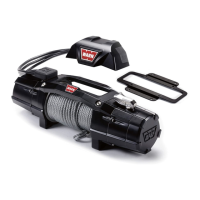
Trigger Switch
6. Route Red Lead Wire from load limiter
circuit board J3 and black wire from load
limiter J4 through wire guides up in to
handle to Trigger Switch (Red to B+,
Black to B-) Black wire is connected to
black wire from rocker switch.