Pipe connections
Control air to by-pass/waste-gate valve311
Air supply for flushing316
Instrument air inlet320
8.3.1 Starting air compressor unit (3N02)
At least two starting air compressors must be installed. It is recommended that the compressors
are capable of filling the starting air vessel from minimum (1.8 MPa) to maximum pressure in
15...30 minutes. For exact determination of the minimum capacity, the rules of the classification
societies must be followed.
8.3.2 Oil and water separator (3S01)
An oil and water separator should always be installed in the pipe between the compressor
and the air vessel. Depending on the operation conditions of the installation, an oil and water
separator may be needed in the pipe between the air vessel and the engine.
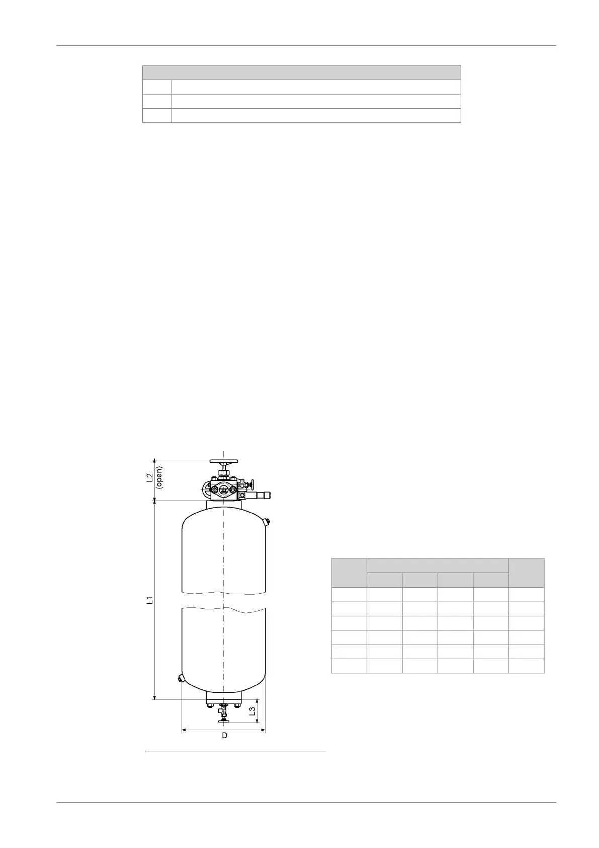
8.3.3 Starting air vessel (3T01)
The starting air vessels should be dimensioned for a nominal pressure of 3 MPa.
The number and the capacity of the air vessels for propulsion engines depend on the
requirements of the classification societies and the type of installation.
It is recommended to use a minimum air pressure of 1.8 MPa, when calculating the required
volume of the vessels.
The starting air vessels are to be equipped with at least a manual valve for condensate drain.
If the air vessels are mounted horizontally, there must be an inclination of 3...5° towards the
drain valve to ensure efficient draining.
Fig 8-4 Starting air vessel
Weight
[kg]
Dimensions [mm]Size
[Litres]
DL3
1)
L2
1)
L1
4504801332433204500
81065013325535601000
98080013325529301250
115080013325534601500
131080013325540001750
149080013325546102000
1)
Dimensions are approximate.
DAAB605814 8-7
8. Compressed Air SystemWärtsilä 46F Product Guide
 Loading...