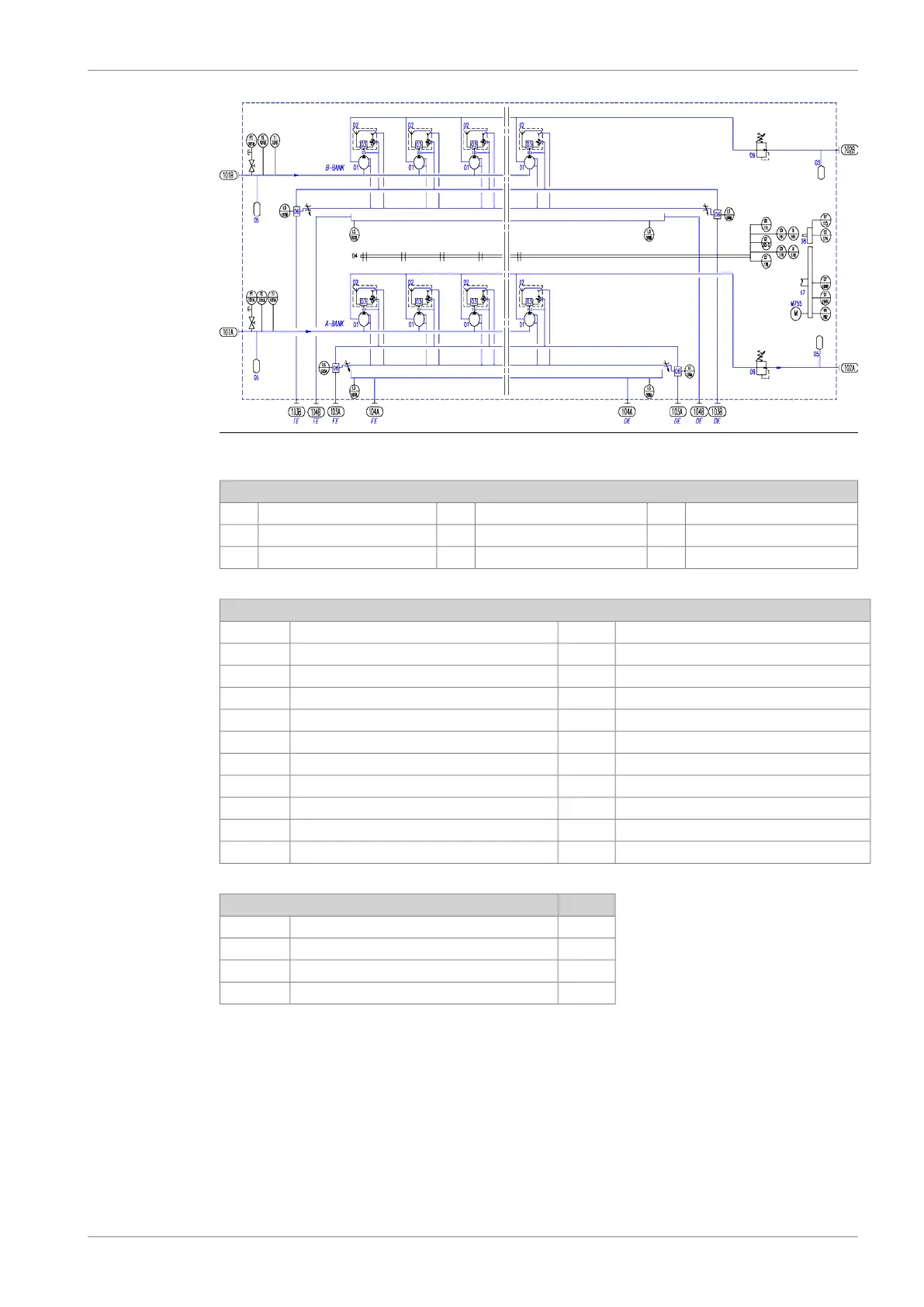
Fig 6-2 Internal fuel system, V-engine (DAAR030664)
System components
Flywheel07Fuel & timing rack04Injection pump01
Camshaft08Pulse damper05Injection valve02
Pressure regulating valve09Fuel oil leakage collector06Switching valve03
Sensors and indicators
Engine speed 1 (safety)ST173Fuel oil pressure, engine inletPT101A/B
Engine speed 2 (safety)ST174Fuel oil temperature, engine inletTE101A/B
Timing rack actuatorCV178Fuel oil temperature, engine inlet (local)TI101A/B
Timing rack positionGT178Fuel oil temperature, engine outletTE102A/B
Engine speed for torsional vibrationST191Fuel oil (clean) leakage - DELS103A/B
Engine speed, primeST196PFuel oil (clean) leakage - FELS106A/B
Drive unit for CV161U161Fuel oil (dirty) leakage - FELS107A/B
Engine speed, back-upST196SFuel oil (dirty) leakage - DELS108A/B
Turning gear engagedGS792Fuel rack actuatorCV161
Electric motor for turning gearM755Fuel rack positionGT165-2
Drive unit for CV178U178Stop lever in stop positionGS171
SizePipe connections
DN32Fuel inlet101A/B
DN32Fuel outlet102A/B
DN25Leak fuel drain, clean fuel103A/B
DN25Leak fuel drain, dirty fuel104A/B
The engine is designed for continuous operation on heavy fuel oil (HFO). On request the engine
can be built for operation exclusively on marine diesel fuel (MDF). It is however possible to
operate HFO engines on MDF intermittently without any alternations. Continuous operation
on HFO is recommended as far as possible.
If the operation of the engine is changed from HFO to continuous operation on MDF, then a
change of exhaust valves from Nimonic to Stellite is recommended.
DAAB605814 6-9
6. Fuel Oil SystemWärtsilä 46F Product Guide