9
Installation
Electrical installation
All electrical installations are to be carried
out by licenced personnel.
Although the machines are equipped with
thermal overloads in the motor windings a
separate three-phase common-trip circuit breaker
must be installed for all three-phase machines.
For proper overcurrent protection, check the data
plate at the rear of the machine. Also consult
local electrical code for special requirements.
Use inverse-time circuit breaker only.
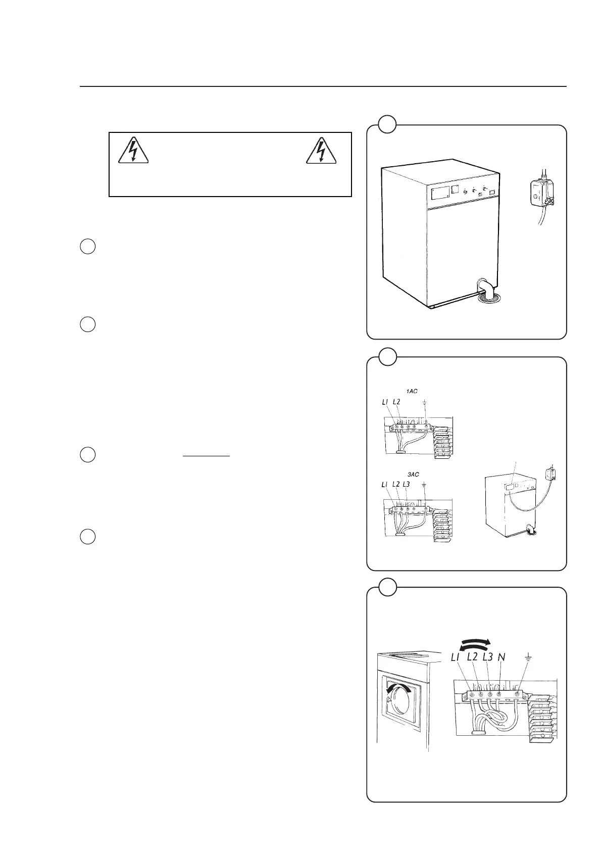
Connect L1, L2, L3 and ground wires according
to the markings of the terminal block at the upper
left rear corner of the machine. The cable is to
hang in a large loose loop, supported by the clip
of the terminal block.
After installation, do the following for 3-phase
machines:
Check the incoming power for a high voltage or
"stinger" leg. This will usually measure higher
than 150 Volts
to ground. If present, connect that
line to L2 on the terminal block.
For 3-phase machines start the machine and
check that the drum rotates in the ccw direction
during extraction, when seen from the front. If the
drum rotates in the wrong direction interchange
lines L1 and L3 at the power connection termin-
als.
Recommended overcurrent protection
W75 3-phase – 15 A max
W75 1-phase – 20 A max
W105 3-phase – 15 A max
W105 1-phase – 20 A max
W125 3-phase – 15 A max
W125 1-phase – 20 A max
W185 3-phase – 15 A max
W185 1-phase – 20 A max
Signals for external supply (non-metered
machines).
At the rear of the machine, next to the incoming
lower terminal block, there is another terminal
block for connection of signal wires to an external
supply dispenser. The connection points are
marked 1, 2, 3 and C (common).
8
1830
9
1838
10
Fig.
8
Fig.
9
Fig.
10
Fig.
10
1839