630 En/EnN Installation, operating, and maintenance manual
m-630en-en-01 1
Contents
1 Declaration of conformity 5
2 Declaration of incorporation 6
3 When you unpack your pump 7
3.1 Unpacking your pump 7
3.2 Packaging disposal 7
3.3 Inspection 7
3.4 Components supplied 7
3.5 Storage 7
4 Information for returning pumps 8
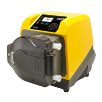
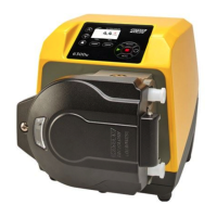
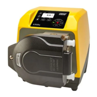
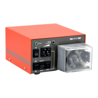
5 Peristaltic pumps - an overview 8
6 Warranty 9
7 Safety notes 10
8 Pump specifications 13
8.1 Specification ratings 13
8.2 Weights 13
8.3 Pumphead options 14
9 Good pump installation practice 15
9.1 General recommendations 15
9.2 Dos and don'ts 16
10 Pump operation 17
10.1 Keypad Layout and Key IDs 17
10.2 Starting and stopping 18
10.3 Using up and down keys 18
10.4 Maximum speed 18
10.5 Change rotation direction 18
11 Connecting to a power supply 19
11.1 Conductor colour coding 20