12 PROFIBUS control wiring
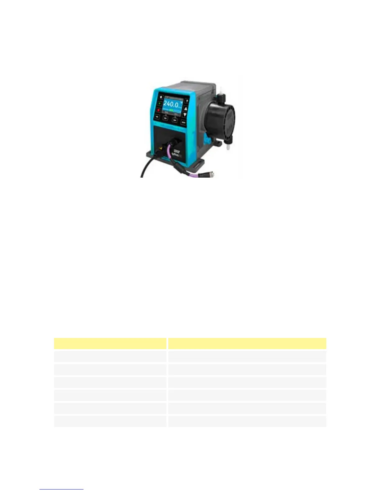
Interfacing the pump with the PROFIBUS network is by means of an M12 connector mounted
on a flying lead on the front of the pump.
It is the user’s responsibility to ensure the safe and reliable operation of the pump under
PROFIBUS control.
Note: The transmission speed is limited to a maximum of 1.5Mbit/s.
12.1 PROFIBUS installation
All devices in the bus system must be connected in a line. An IP66 rated T adaptor should
be used to connect the pump to the PROFIBUS line. A maximum of 32 stations (to include
master, slaves and repeaters) are possible and both the beginning and the end of the cable
must be terminated with a terminating resistor.
The M12 socket provided for PROFIBUS installation is IP66 rated. To maintain an IP66 rated
system, the PROFIBUS cable, T adaptors and terminating resistors used must be fitted with
IP66 rated M12 industrial connectors.
Note: To prevent low- frequency ground loops, screening which is earthed at one end
should be used. To counter magnetic HF pick-up, shielding earthed at both ends as well as
twisted conductors should be used, this will have no effect against electrical HF pick-up.
The permissible overall length of the bus cabling will vary according to the required bit
rate. If a longer cable or higher bit rate are required repeaters should be used. The
maximum bit rates achievable are shown in the table below.
Bit rate (Kbit/s) Max. length of type A bus cable (m)
1500 200
500 400
187.5 1000
93.75 1200
19.2 1200
9.6 1200
Note: Total stub length should not exceed 6.6m.
m-qdos-en-02 40
 Loading...