Parts Diagrams
Part Number 95301T
Note: This asssembly does
not include a magnet disk or
drive motor and must be
ordered separately.
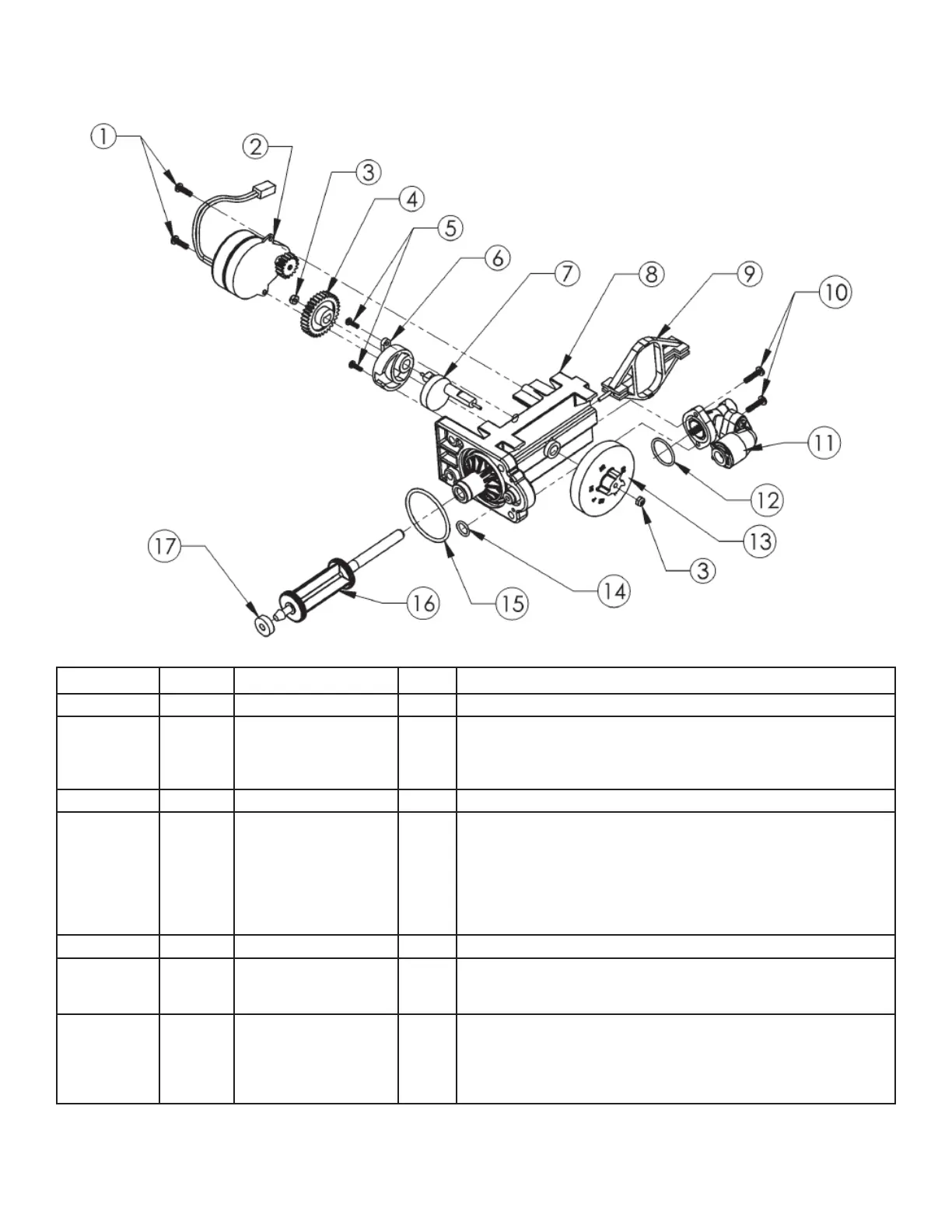
Figure 15
Figure# Part# Item Qty. Description
1 90802 Screw Secures motor to endcap assembly.
2 90217 Drive Motor - 12V The Drive Motor is held in place by two 1/2” screws. The screws
should be “snug.” The brass pinion gear on the Motor should engage
the plastic Drive Gear. The wires should be securely fastened to the
Control.
3 93891 1/4” Hex Nut Secures drive gear and magnet disc to end cap assembly.
4 93238 Drive Gear The Drive Gear is assembled to the Piston Slide Cam by means of a
“keyed” opening which transfers the “torque” generated by the Drive
Motor to the rest of the drive system. If the drive system becomes
jammed, this opening can become “rounded” causing the gear to
turn, but not the Piston Slide Cam. If this occurs, clear the jam and
replace the Drive Gear and Piston Slide Cam
(Part No. 93217).
5 90809 Screw
6 93219 Piston Slide
Cam Cover
The cover secures the Piston Slide Cam (93217) in place and acts
as a bushing
for the Cam Shaft.
7 93217 Piston Slide Cam This is the “heart” of the drive system. There is a threaded stainless
steel shaft that runs through the main drive axle. The Drive Gear is
attached at the short end and the Magnet Disc at the other end. The
Piston Slide Cam is assembled inside of the Piston Slide (93216).
This Cam Shaft should turn freely before the Motor is assembled.
26