Parts Diagrams
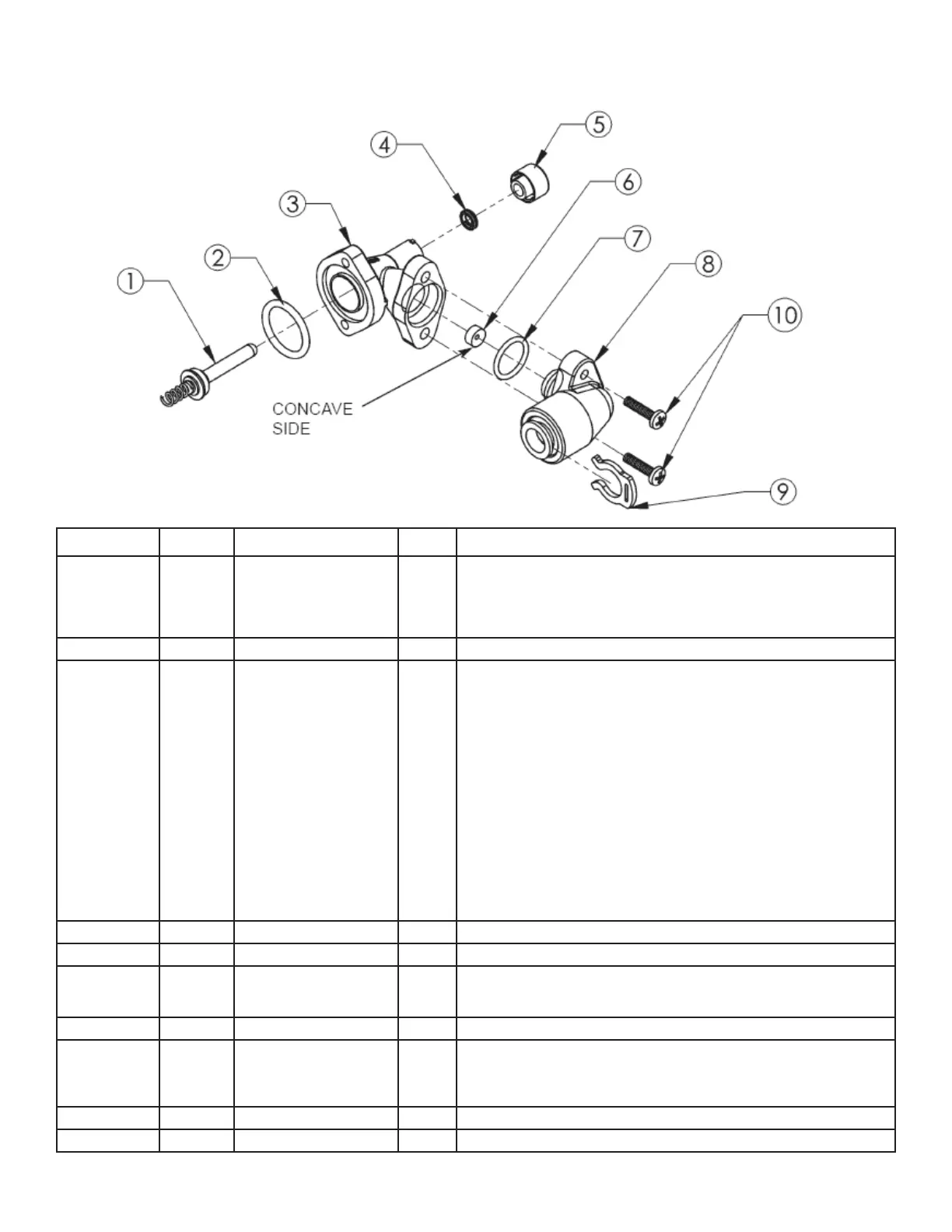
Figure 16
Part Number 93601
Brine Valve Housing Assembly
Figure# Part# Item Qty. Description
1 93620 Piston Assembly 1
The Piston should have a gasket on the shaft side of the fl ange and a spring
pressed onto a boss on the other side. The gasket should be free of defects
such as cuts or debris. The Piston is Tefl on coated and should be free of
scratches. The Piston should move freely in the housing; silicone lubrication
is recommended on the Piston shaft.
2 90821 O-Ring 1
Seals the brine valve to the drive endcap.
3 93260 Housing 1
Should have a Quad-ring for the Piston seal. The Quad-ring (4) is held in
place by the brine valve retainer (5). The brine valve housing has four retain-
ing lugs that secure the brine valve retainer. Just inside the entrance hole for
the Brine Piston (1) is a concave seat area that must be free of defects such
as nicks, indentations or debris. If any defects are detected by visual inspec-
tion, repair or replace as needed.
To replace the Quad-ring, it will be necessary to remove the brine valve
housing assembly from the drive end cap (after by-passing and depressuriz-
ing the conditioning appliance). Push the piston assembly (1) out of the hous-
ing. To remove the brine valve retainer (5) push in and turn “clockwise” to
unlock the retainer. CAUTION! Do not attempt to remove the retainer with the
piston assembly in place. This will damage the housing and/or the retainer.
Push the piston back into the housing to dislodge the old Quad-ring (4) and
discard it. Remove the piston, insert the new Quad-ring and lock the retainer
onto the housing by pushing in and turning “counterclockwise” to secure the
Quad-ring. Replace the piston assembly and attach the brine valve assembly
to the drive end cap and restore service to the conditioning appliance.
4 93878 Quad Ring 1
Seals piston and housing assembly.
5 93254 Quad Ring Retainer 1
Holds quad ring in place.
6 908843 .5 gpm Flow Control 1
The Flow Control has two distinct and different sides. One is “fl at;” the other
is “concave.” The button should be centered in the housing opening with the
concave side facing the Housing Cap.
7 93805 O-Ring 1
Seals the housing cap to the housing.
8 93243 Housing Cap Assembly 1
Held in place by two 5/8” machine screws that engage the Housing fl ange.
An O-ring seals the Housing Cap and Housing. Place the O-ring into the
housing opening, lubricate with silicone grease and then use a twisting action
to insert the Housing Cap.
9 200199 Clip 1
Locking Clip.
10 90818 Screw 2
Secures housing cap to housing.
28