SmartPlate Installation, Operation & Maintenance Manual
CHAPTER 4 – ADJUSTMENT
OMM-0069_0H • SP-100 • 1/30/2020 Technical Support • (800) 526-0288 • Mon-Fri, 8 am - 5 pm EST Page 33 of 134
SETPOINT TEMPERATURE ADJUSTMENT Instructions
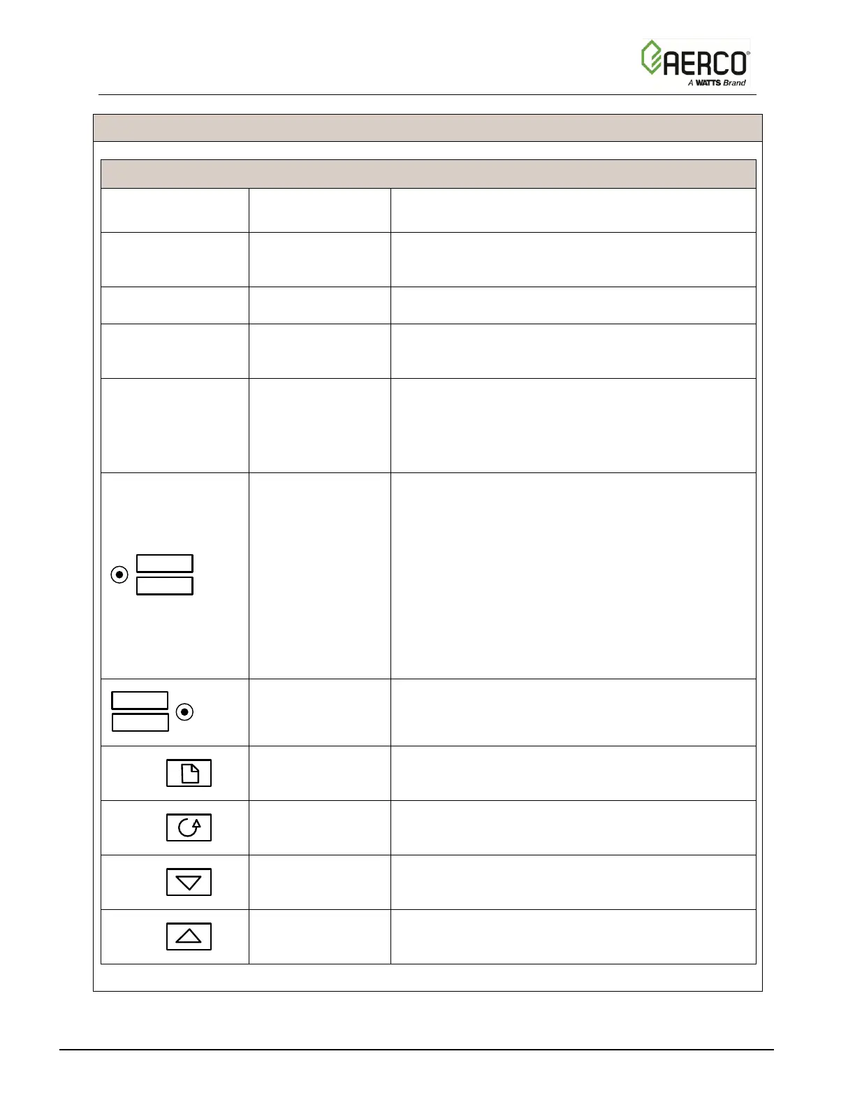
TABLE 4-2. Temperature Controller Operating Controls, Indicators & Displays
OP1 lights when a 0 to 10 VDC signal is being
supplied to the ECSSP Valve Actuator
Not used for the ECS/SP application
Not used for the ECS/SP application
Remote Setpoint
Indicator
REM lights when the ECS/SP is set up to be
controlled by a Remote (Modbus) signal.
REM will also flash when Modbus communication
is active.
Auto/Manual Button
and Indicators
When button is pressed, the Controller is toggled
between the automatic (AUTO) and manual (MAN)
modes. When first set to manual the valve will
close and show zero percentage (0 %) on the
display.
• AUTO lights when in the automatic mode.
(Setpoint temperature setting appears in lower
display)
• MAN lights when in the manual mode.
(Valve percent open appears in lower display)
Run/Hold Button
and Indicators
Not used for ECS/SP application
Press Page button to select a new list of
parameters
Press Scroll button to select a new parameter in a
list
Press to decrease the value shown in the lower
display
Press to increase the value shown in the lower
display

 Loading...

