EasyManua.ls Logo

wattstopper DT-200 User Manual

wattstopper DT-200
12 pages
To Next Page IconTo Next Page
Page #1 background imageLoading...
Page #1 background image
DT-200
version 2
Dual Technology • Low Voltage
Occupancy Sensor
with Isolated Relay and Manual On features
SPECIFICATIONS
Voltage ............................................................. 18-28VDC/VAC
Current Consumption ......................................................43mA
Power Supply ..................................WattStopper Power Packs
Isolated Relay Rating ...................................... 1A @30VDC/VAC
Operating Temperature ..................... 32° to 131°F (0° to 55°C)
Light Level One-Step Adjustment .....................10FC to 300FC)
Time Delay Adjustment .................................... 5 to 30 minutes
Walk-Through Mode ...3 minutes if no activity after 30 sec.
Test Mode .5 sec. upon intial power-up or DIP switch reset
PIR Coverage (Typical) .................................................. 1000 ft
2
Sensitivity Adjustment Automatic or Low (DIP switch setting)
Ultrasonic Coverage (Typical) ................................800-1200 ft
2
Sensitivity Adjustment ..... Minimum to Maximum (trimpot)
Frequency .................................................................. 40kHz
Installation Instructions
U.S. Patent: 5,189,393
Santa Clara, CA 95050
Question and Answer IconNeed help?

Do you have a question about the wattstopper DT-200 and is the answer not in the manual?

wattstopper DT-200 Specifications

General IconGeneral
Brandwattstopper
ModelDT-200
CategoryAccessories
LanguageEnglish

Summary

Specifications

Unit Description

Dual Technology Operation

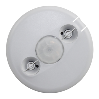
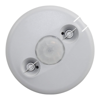
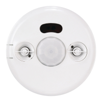
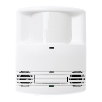
Combines PIR and ultrasonic technologies to prevent false triggers.

Power and Relay Functionality

Operates on 24VDC and features an isolated relay for HVAC/EMS interfacing.

Coverage Pattern

Placement Guidelines

Wiring Directions

Low Voltage Connection

Connecting the low voltage power wires to the sensor.

Single Lighting Load Control

Wiring for controlling a single lighting load via occupancy.

Momentary Manual Switch

Connecting a manual switch for additional control.

Isolated Relay Wiring

Connecting the isolated relay output wires for specific applications.

Mounting the Sensor

Ceiling and Wall Mounting

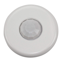
Instructions for mounting the sensor to ceilings or walls using brackets.

Sensor Angle Adjustment

Adjusting Mounting Angle

Using LEDs to guide angle adjustment for optimal coverage.

Sensor Adjustment

Testing Occupancy Sensors

Step-by-step guide to test sensor functionality and LEDs.

Occupancy Logic

Logic Configurations

Eight logic configurations for occupancy triggers via DIP switches.

Time Delay Settings

Using DIP switches 4, 5, & 6 to set the time delay.

Auto and Walk-Through Modes

Explanation of Auto time delay and Walk-through mode functionality.

Manual On Function

Manual Switch Integration

Using momentary switches for manual ON control.

Troubleshooting

Lights Do Not Turn On

Diagnosing issues when lights fail to activate with occupancy.

Lights Do Not Turn Off

Diagnosing issues when lights remain on after no occupancy.

Unwanted Sensor Activations

Related product manuals