b.
For increasing frequency
sweep
with positive
dc input, set dial to
lower frequency limit.
c.
For decreasing frequency sweep with nega-
tive
dc input, set
dial
to
upper frequency
limit.
6.
To sweep the audio range
from
20
Hz
to 20
kHz,
set the controls
to 20
Hz
as
follows:
a. Set the main dial to 0.02.
b. Set the
frequency vernier to the full ccw
position.
c.
Introduce
a 0 to
+5 V ramp into the VCG
input'connector.
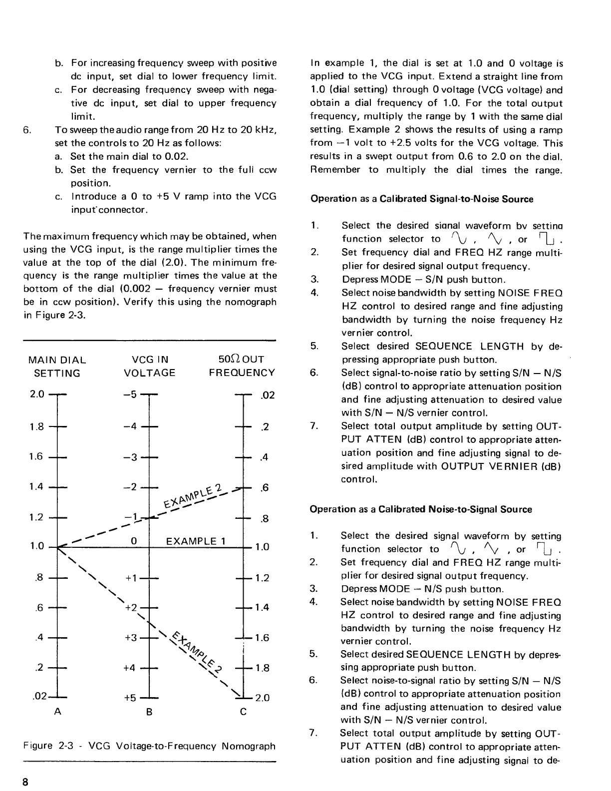
The
maximum frequency which
may be
obtained, when
using
the
VCG input, is the range multiplier times the
value at
the
top of the dial
(2.0).
The minimum
fre-
quency
is the range multiplier
times the
value
at
the
bottom
of the
dial (0.002
—
frequency vernier
must
be in ccw position). Verify this using the nomograph
in Figure
2-3.
MAIN
DIAL
VCG
IN 50HOUT
SETTING
VOLTAGE
FREQUENCY
Figure
2-3
-
VCG Voltage-to-Frequency
Nomograph
In example
1,
the
dial is
set at 1.0
and 0 voltage
is
applied to
the
VCG input.
Extend
a straight
line
from
1.0
(dial setting) through
0 voltage
(VCG
voltage)
and
obtain a dial
frequency
of
1.0. For
the total
output
frequency, multiply the range
by 1 with the
same dial
setting.
Example
2 shows the
results of
using
a
ramp
from
—1
volt
to +2.5 volts for
the VCG
voltage.
This
results in
a swept output from
0.6
to
2.0 on the
dial.
Remember to
multiply the
dial times
the range.
Operation as
a
Calibrated
Signal-to-Noise
Source
1. Select the
desired siqnal waveform
bv settina
function
selector to
f
\j ,
A^
(
or
Tl-
2. Set
frequency
dial and FREQ HZ
range
multi-
plier for desired
signal output frequency.
3. Depress
MODE
—
S/N push
button.
4. Select
noise
bandwidth
by
setting
NOISE FREQ
HZ control
to
desired range
and fine
adjusting
bandwidth
by
turning the noise
frequency Hz
vernier
control.
5. Select desired SEQUENCE
LENGTH
by
de-
pressing
appropriate push button.
6. Select signal-to-noise ratio
by setting S/N
—
N/S
(dB) control to appropriate
attenuation
position
and fine adjusting attenuation
to desired
value
with
S/N
—
N/S vernier control.
7. Select total output
amplitude
by
setting
OUT-
PUT ATTEN (dB) control
to
appropriate
atten-
uation position
and fine
adjusting
signal to de-
sired amplitude with
OUTPUT VERNIER
(dB)
control.
Operation
as a
Calibrated Noise-to-Signal
Source
1. Select
the desired signal waveform
by setting
function
selector
to
r
\j
,
A^
f
or
1l
2. Set frequency
dial and
FREQ HZ range multi-
plier for
desired signal
output frequency.
3. Depress MODE
—
N/S
push button.
4. Select noise
bandwidth
by
setting NOISE
FREQ
HZ control
to
desired
range
and
fine
adjusting
bandwidth
by
turning
the noise
frequency
Hz
vernier
control.
5. Select
desired
SEQUENCE
LENGTH
by
depres-
sing
appropriate push
button.
6. Select
noise-to-signal ratio
by setting
S/N
—
N/S
(dB) control
to appropriate
attenuation
position
and
fine
adjusting
attenuation to
desired value
with
S/N
—
N/S
vernier
control.
7. Select
total
output amplitude
by setting OUT-
PUT
ATTEN (dB) control
to
appropriate
atten-
uation
position and fine
adjusting
signal to
de-
8