sired amplitude
with OUTPUT
VERNIER (dB)
control.
'Operation as a
Random FM
Source
Before
using the
generator as a random
FM source,
please note the
following.
4.
Select
desired
SEQUENCE
LENGTH
by
depres-
sing appropriate push button.
5. Select
noise amplitude
by
setting OUTPUT
ATTEN (dB)
control to appropriate
attenuation
position and
fine adjusting noise to
desired
amplitude
with
OUTPUT
VERNIER (dB)
con-
trol.
The
frequency
of
the
generator is being
varied
or
modulated
by
a
changing voltage in
the same
way as
described
in
"Operation
as
a Voltage
Controlled Gen-
erator."
However, instead
of
using a dc
ramp,
or
ac
signal, a
random analog voltage is
used.
When
the FM
push button is
depressed, the
analog noise
is
injected
internally into the
VCG circuit;
therefore, the
modu-
lation is
created
by
random noise. The S/N
—
N/S (dB)
knob
controls ths msximum amount
of
frscjusncy
deviation, since it
controls the amplitude
of the
noise.
Bandwidth
of the FM signal is
controlled by
the
NOISE FREQ
HZ control. Using the
generator
in the
FM
mode
may
be accomplished as
follows:
1.
Select the desired
signal
waveform
by
setting
function selector to
/
\y ,
/
\/
,
or
Hu
•
2. Set
frequency dial and FREQ
HZ
range
multi-
plier for desired center output
frequency.
3.
Depress MODE
—
FUNC and FM push buttons.
4.
Select the
bandwidth
by
setting NOISE FREQ
HZ control
to desired
range
and
fine adjusting
frequency
by
turning
the noise frequency
Hz
vernier control.
5.
Select desired SEQUENCE
LENGTH
by
depres-
sing
appropriate push button.
6.
Select
signal
frequency
deviation
by
setting
S/N
—
N/S (dB)
controi
to appropriate
attenua-
tion
position
and
fine adjusting
attenuation to
desired
deviation with S/N
—
N/S
vernier control.
7. Select
output
signal amplitude
by
setting OUT-
PUT
ATTEN (dB)
control to appropriate atten-
uation position and
fine adjusting signal to de-
sired
amplitude with OUTPUT VERNIER (dB)
control.
Operation
as a
Digital or Analog Noise Source
1.
Set
function
selector to digital
or
analog noise
position.
2.
Depress MODE
—
FUNC push button.
3.
Select clock frequency for digital
or bandwidth
for
analog
noise
by
setting NOISE
FREQ
HZ
control to
desired
range
and
fine adjusting fre-
quency
by
turning
the
noise
frequency Hz ver-
nier control.
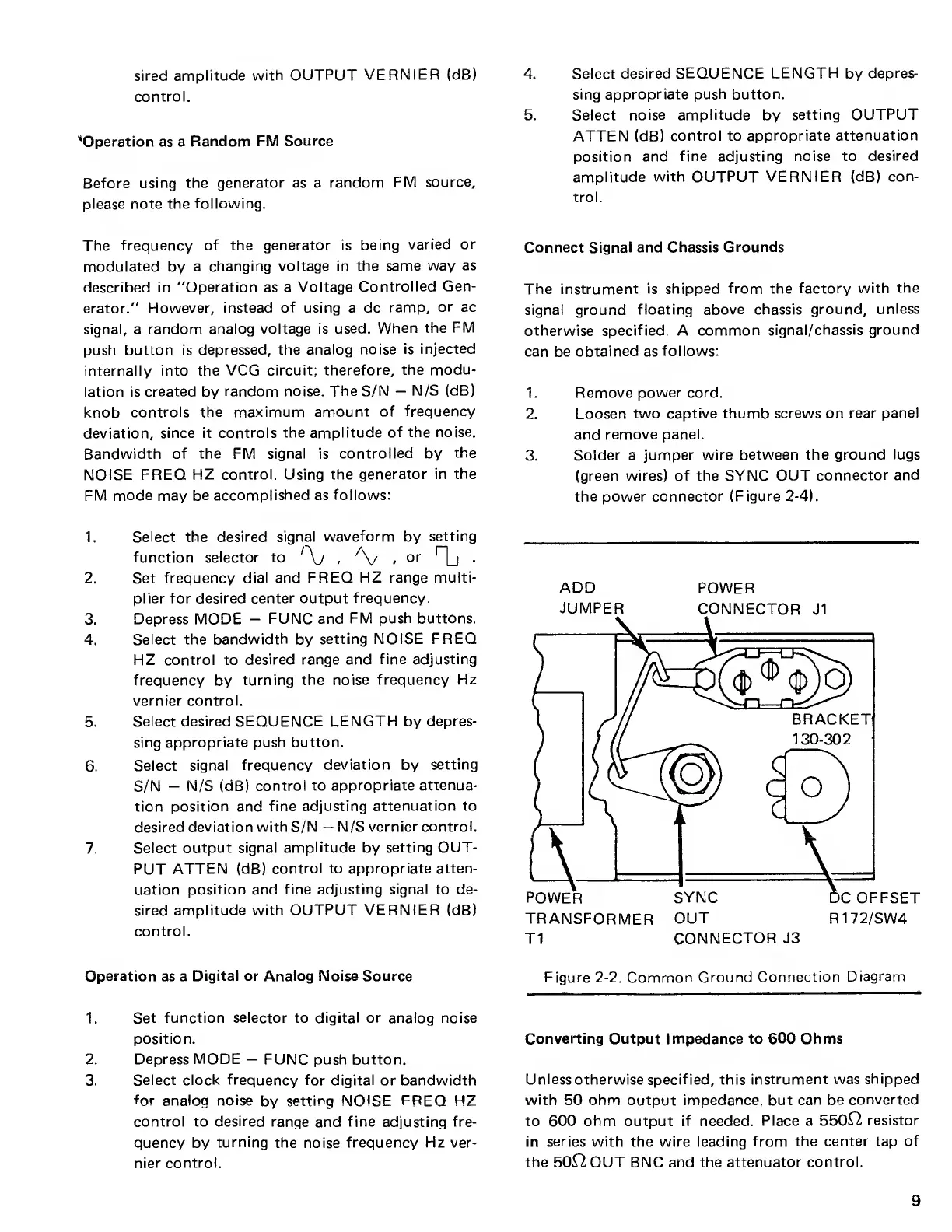
Connect
Signal
and Chassis
Grounds
The instrument
is shipped from the
factory with
the
signal ground
floating above chassis
ground,
unless
otherwise specified. A
common
signal/chassis ground
can be
obtained
as
follows:
1.
2
.
3.
Remove
power cord.
I oocpn tiAirv
oon+iwo
thiimh coroiA/c n n roar nanol
|_WU
jC II
L
V V W
Ll« V LI IUI IU
Wl Ul/lIJ
*-*
I •
I V/WI
i'"
and
remove panel.
Solder a
jumper wire
between the ground
lugs
(green
wires) of the SYNC OUT
connector
and
the
power connector
(Figure
2-4).
ADD
POWER
JUMPER
CONNECTOR
J1
Figure
2-2.
Common
Ground
Connection
Diagram
Converting Output Impedance to 600 Ohms
Unless otherwise
specif ied, this
instrument was
shipped
with
50
ohm
output impedance, but
can be
converted
to 600
ohm
output
if
needed.
Place a
550^2
resistor
in
series
with the wire leading
from the
center tap
of
the 50^2 OUT BNC and the
attenuator
control.
9