112 CHAPTER 10 CLICK 112/114
One benet of using DIP switches to congure is that if you ever have a eld service call and
need to replace a Click 112/114, all you need to do is match the pattern of the DIP switches
on the card you are replacing. is paradigm will even work in situations where the old rack
card will not power up.
On the other hand, a benet of using the soware conguration is that you can remotely
manage the conguration of the cards, if you are connected to them. In this paradigm, it
becomes the user’s responsibility to keep a record of how each card was congured, which
is easy to do using Click Supervisor.
Note
The Click 112/114 receives datagrams from the connected SmartSensor. These data-
grams must be mapped to device outputs (covered in the next section). If the Click
112/114 does not receive a datagram describing the device’s channels for ten seconds,
the device will enter fail-safe mode. In fail-safe mode, all outputs will assert a detec-
tion condition, and will continue to do so until the device receives a datagram that
updates the state of its configured channels.
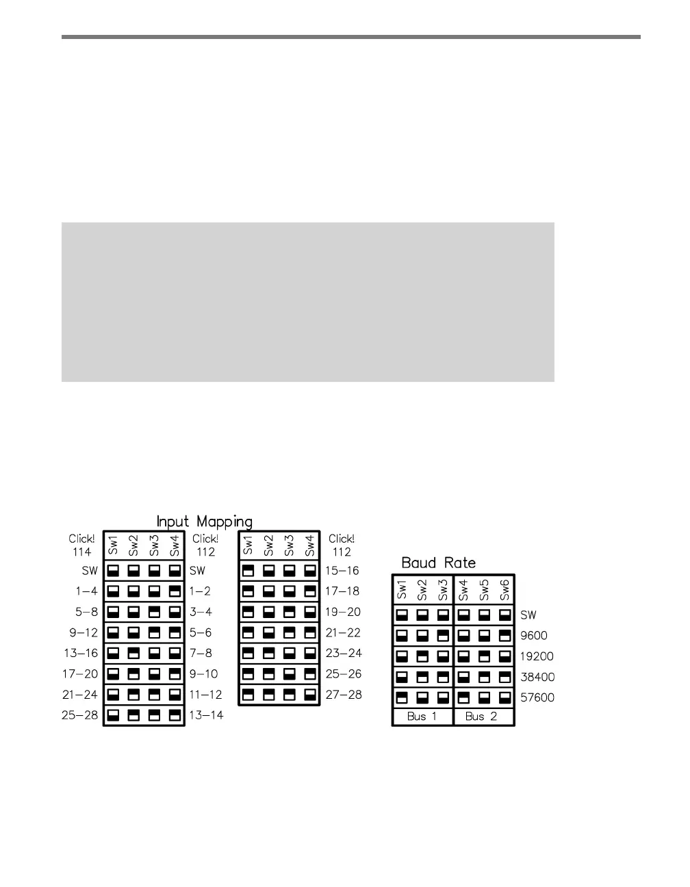
DIP Switches
e DIP switches are located on the lower part of the circuit board, behind the faceplate.
Printed on the board above the switches is information about conguring the card using the
DIP switches, as shown in Figure 10.4.
Figure 10.4 – Click 112/114 DIP Switches
e Click 112/114 feature two DIP switches labeled S4 and S5 on the silk screen. e
switches are used to congure a total of three dierent parameters:
Bus 1 baud rate