134 CHAPTER 12 CLICK 172/174
Physical Features
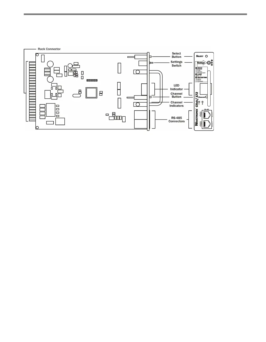
e following sections describe the features of the Click 172/174 cards (see Figure 12.2):
Figure 12.2 – The Click 172
Communication Port
e RJ-11 ports on the front of the Click 172/174 cards allow you to easily connect to a
Click 200 and to daisy-chain multiple cards to one RS-485 bus.
Configuration Features
e front of the device has two push-buttons. e Select button lets you cycle through the
operating modes, inputs and run settings on the display screen. e Channel button allows
you to cycle through the channels only when the Settings switch is in position 2 (Lane).
e face plate also features the Settings switch, which allows you to switch between the
two programming states (Mode and Lane) and run the mode you have selected (Run). e
information below describes the three dierent switch position settings:
Position 1 (MODE) – Allows you to select an operating mode.
Position 2 (LANE) – Allows you map an input channel to a corresponding output
channel.
Position 3 (RUN SETTING) – Allows you to run the selected operating mode. While in
this position, the Click 172/174 is able to display the speed, count or low power (LP)
on the display.
e Display screen on the front of the device can show one of the following:
Operating Mode (Pr, Pu, AC, 1L)
Lane Names (shows two symbols to identify the lane)
Speed
Count