CHAPTER 1 THE POWER PLANT 13
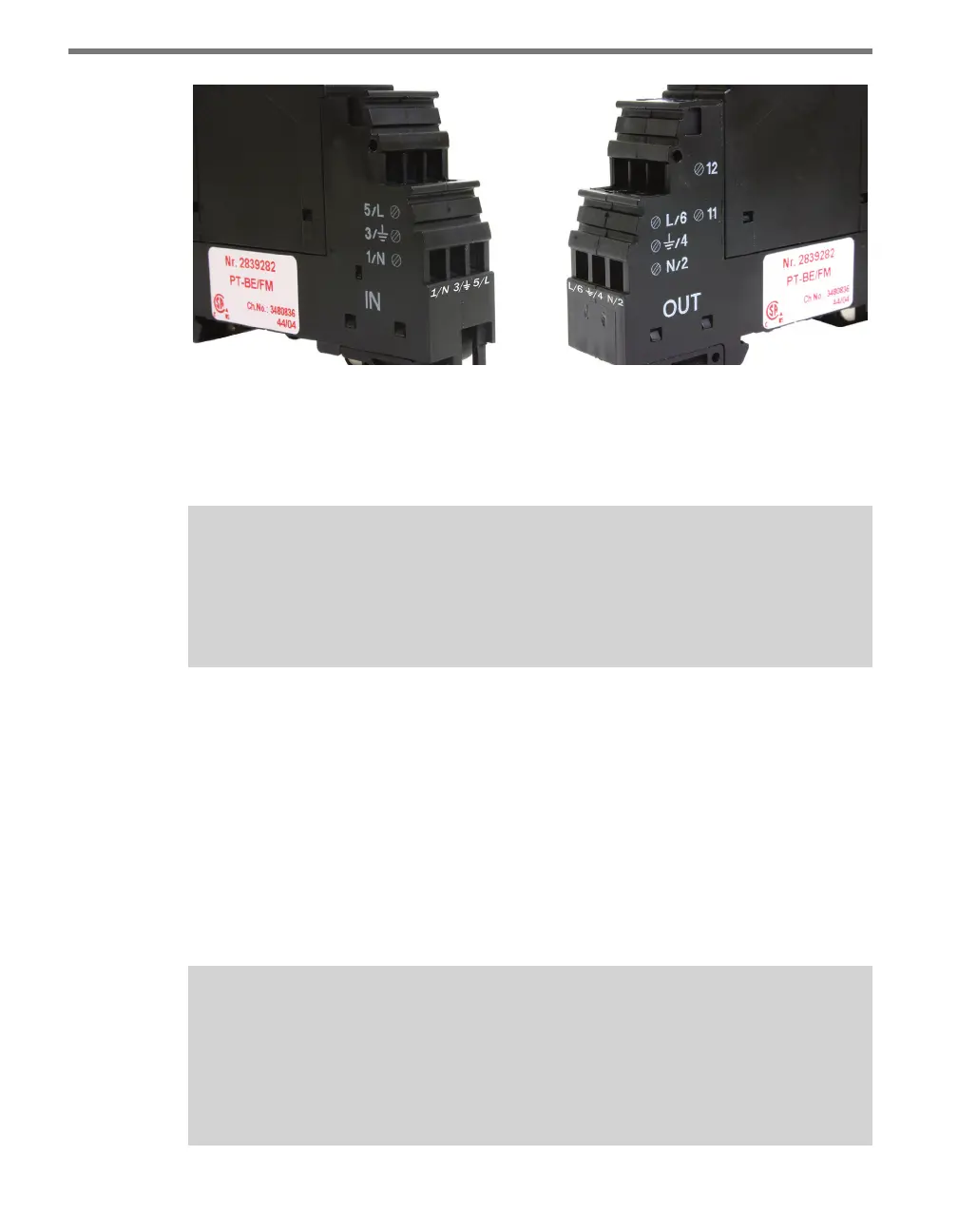
Figure 1.2 – Click 230 Screw Terminals (labels beneath terminals have been added)
Screw terminals 3 and 4 are directly bonded via the metal mounting foot of the base ele-
ment to the DIN rail. ere is no need for any additional grounding between terminals 3
and 4 and the DIN rail.
Note
If you are using a Click 211 in your installation, the configuration of the power plant
will dier slightly from what is listed in this chapter, starting at this point in the
installation process. See the Click 211 chapter of this manual for more information.
Connecting Power
e nal component of the power plant is the AC to DC converter. e Click line features
several such converters. e Click 201/202/204 are AC to DC power supplies that provide
DC power to every Click product mounted on the DIN rail. e Click 201 provides 1 A, the
Click 202 provides 2 A and the Click 204 provides 4 A.
e screw terminals on the top and bottom of the Click 201/202/204 can be unplugged
from the module, allowing you to pre-wire power before the nal installation. e screw
terminal blocks are red-keyed, allowing the block to plug back into only one specic jack.
Note
If you prefer, instead of the Click 201/202/204, you can use the Click 203, which is a
combination UPS and battery. This set of modules will convert AC to DC and provide
uninterrupted power to your equipment. See the Click 203 chapter in Part II of this
document for more information.