150 CHAPTER 13 CLICK 200
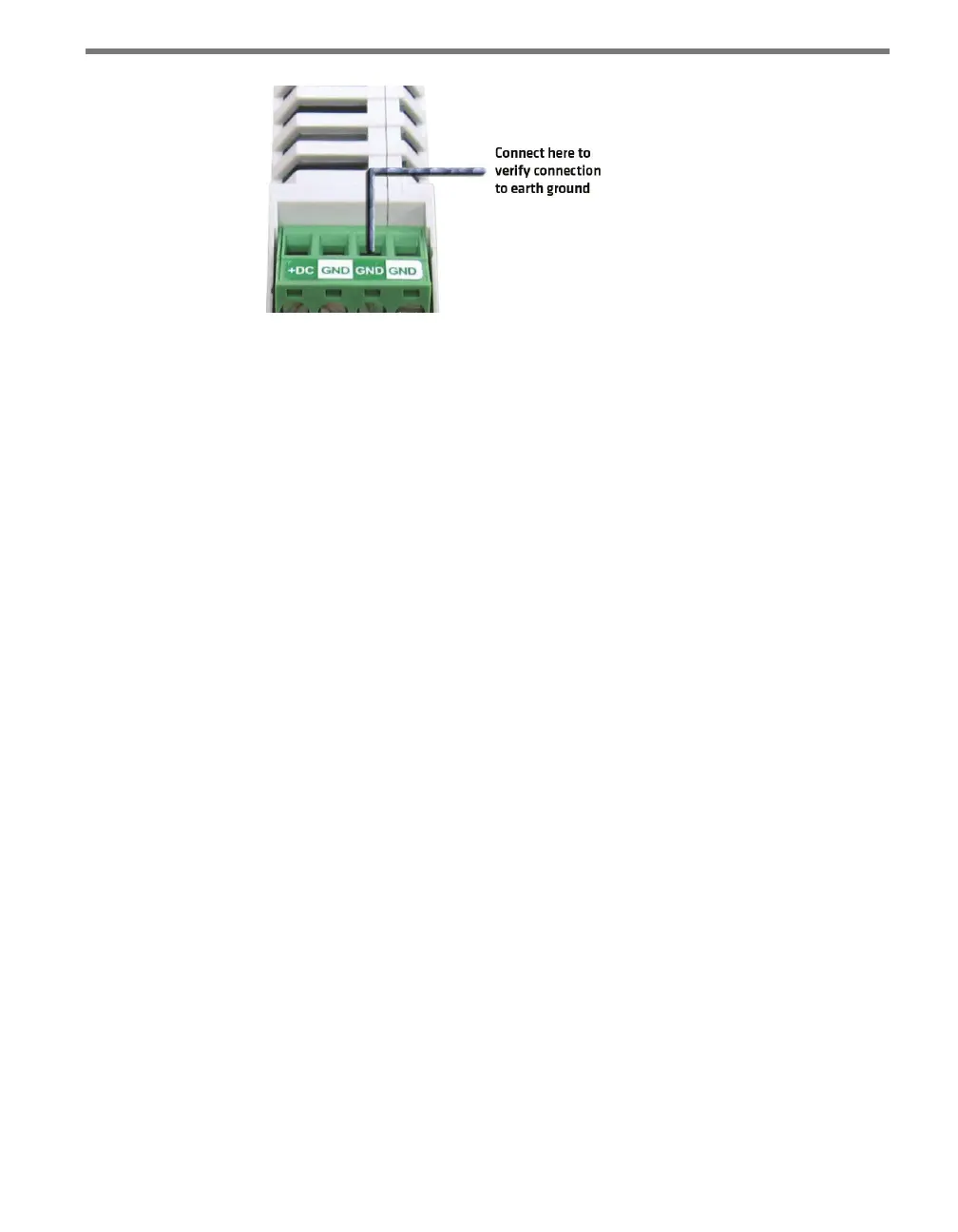
Figure 13.5 – Verifying Earth Ground
3 e resistance should measure less than one ohm. If not, the most likely problem is the
DIN rail is not making connection to earth ground through the chassis of the cabinet.
e Click 200 cards have a connector on the bottom that snaps on the DIN rail that provides
the connection to earth ground. If the DIN rail is not making a good connection to earth
ground, connect a 16 AWG (or larger) wire to the DIN rail with a bolt and run that wire
directly to an earth ground terminal.
Verify Communication
Follow the steps below to verify the communication connections:
1 Check the RS-232 connection by plugging a straight-through RS-232 cable between a
laptop and the DB-9 connector on the Click 200.
2 Launch SmartSensor Manager and connect via a serial connection. If there are prob-
lems connecting, verify that the cabling is set up correctly.
3 Check the RS-485 connection to the SmartSensor using a Click 304 RS-232 to RS-485
converter. Attach the Click 304 to the T-bus (see Chapter 2 for more on T-buses) and
then plug a straight-through RS-232 cable between a laptop and the DB-9 connector
on the faceplate of the Click 304.
4 Launch SmartSensor Manager and connect via a serial connection. If there are prob-
lems connecting, verify that the cabling is set up correctly.
Once communication and ground connections have been veried, the installation of the
Click 200 is complete.