168 CHAPTER 18 CLICK 221
Physical Features
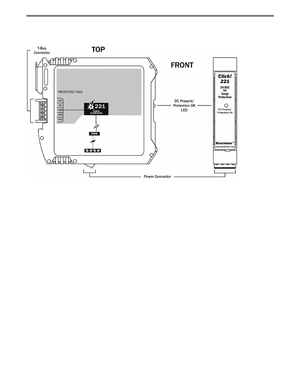
Figure 18.2 – Diagram of the Click 221
e bottom of the Click 221 has a screw terminal block with four screw terminals—+DC,
-DC and two PE terminals—for DC power.
e back of the Click 221 features a 5-position connector that plugs into a T-bus connector
and provides power to the device. It also passes that power to all other devices on the T-bus.
A pinout diagram is provided on each individual unit as a reference in the eld.
e faceplate has an LED used for monitoring the device: if the LED is on, the device has
power and the surge protection is functional.
Installation
To install and wire the Click 221:
1 Mount the Click 221 on the T-bus it is going to protect.
2 Wire power from the DC power source into the +DC and -DC terminals on the bottom
of the device.
3 Wire from one of the PE terminals to a good earth ground. If the device is in a cabinet,
there will likely be a central grounding point—such as a grounding lug—for just such
a purpose.
4 Watch the LED. If it comes on, the device has power and the surge protection is ready.