170 CHAPTER 19 CLICK 222
Physical Features
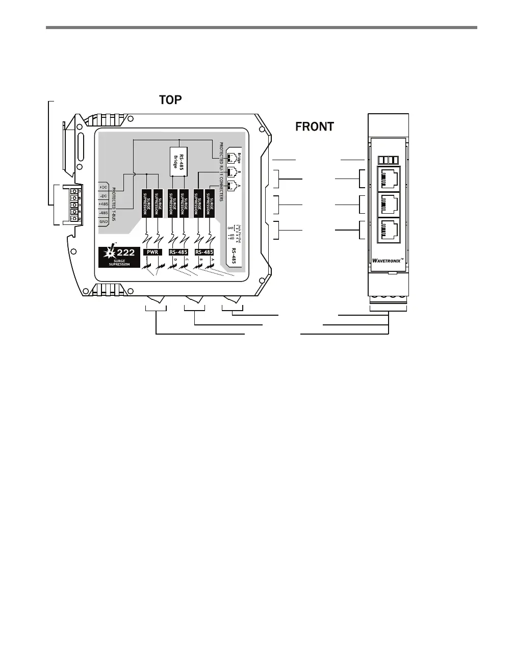
e physical features of the Click 222 include communication and power connections.
LED Indicators
T-Bus
Connector
RS-485
Bridge
Connector
RS-485 B
Connector
RS-485 A
Connector
RS-485 Connector
RS-485 Connector
PWR
DC Surge
OK
TD
RD
Click! 222
System Surge
Protection
www.wavetronix.com
RS-485 A RS-485 B RS-485 Bridge
Control
Data
Data
Figure 19.2 – Diagram of the Click 222
Connections
e faceplate of the Click 222 has three RJ-11 jacks, which provide the following three in-
dependent serial connections:
Topmost jack – control bridge
Middle jack – dedicated communications for sensor 2 detection calls
Lowest jack – dedicated communications for sensor 1 detection calls
e back of the Click 222 features a 5-position connector that plugs into a T-bus connector
and provides power and RS-485 communication to the device. It also passes RS-485 com-
munication from the module to all other devices on the T-bus.
e bottom of the Click 222 has three pluggable screw terminal blocks with four terminals
each, for a total of twelve connections. ese terminals are used for wiring in the cable from
the sensor. e terminals have four dierent RS-485 connections, each consisting of a +485
and a -485 terminal; two of these connections are for detection calls and two for the con-
trol bridge, allowing two sensors to be wired in to each Click 222. is will be explained in
greater detail in the Installation section of this chapter.