240 CHAPTER 28 CLICK 400
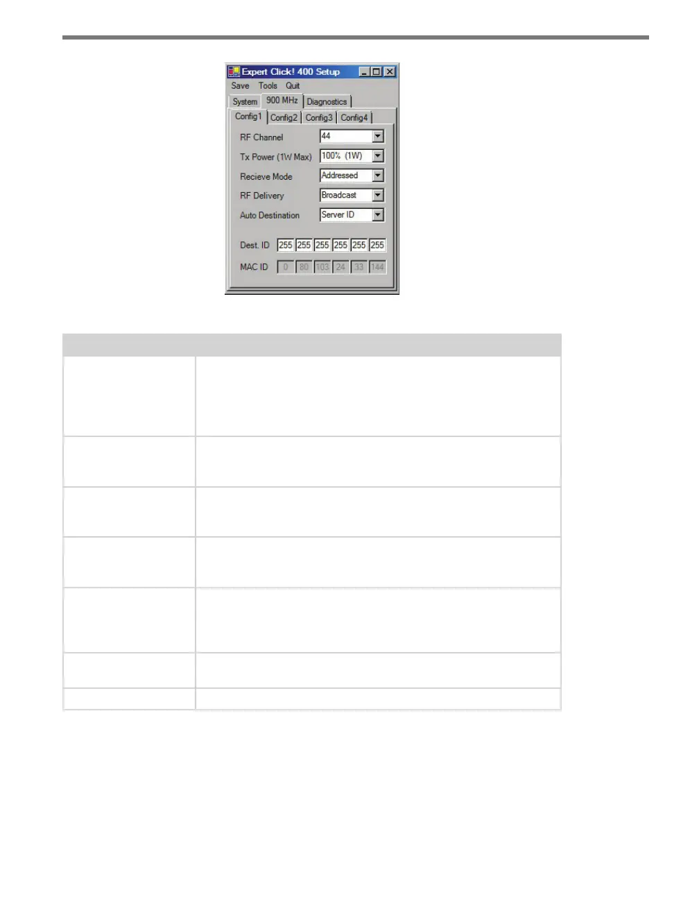
Figure 27.10 – Expert Driver Config 1 Tab
Setting Description
RF Channel
Specifies the frequency channel of the device (the channels range
from 0 to 47). Each client and server must be on the same channel.
It is recommended that each system be on a dierent channel, since
the ranges on these devices extend for miles and sharing the same
channel with another location could result in interference.
Tx Power (1W Max)
Allows you to modify the power level in increments of 10%. The Click
400 transmit power can be reduced to decrease interference caused
by multiple radios.
Receive Mode
Allows you to select which data packets will be received. If the device
is set up as a client, select Address/Broadcast; if the device is set up
as a server, select Address.
RF Delivery
Allows you to send to a specific address or broadcast to all radios. If
the device is set up as a client, select Address; if the device is set up
as a server, select Broadcast.
Auto Destination
Allows you to choose the destination for the data packets. If Destina-
tion ID is selected, the Dest. ID will need to be entered for the Click
400 you are communicating with; if Server ID is selected, the Click
400 will automatically communicate with the Server.
Dest. ID
Allows you to enter the MAC ID of the radio that the Click 400 you’re
configuring should connect to.
MAC ID
The MAC ID is the unique identifier of the MAC layer of the Click 400.
Table 27.7 – Expert Driver Config 1 Tab
e 900 MHz > Cong 2 tab contains channel synchronization settings (see Figure 27.11
and Table 27.8).