246 CHAPTER 29 CLICK 421
Physical Features
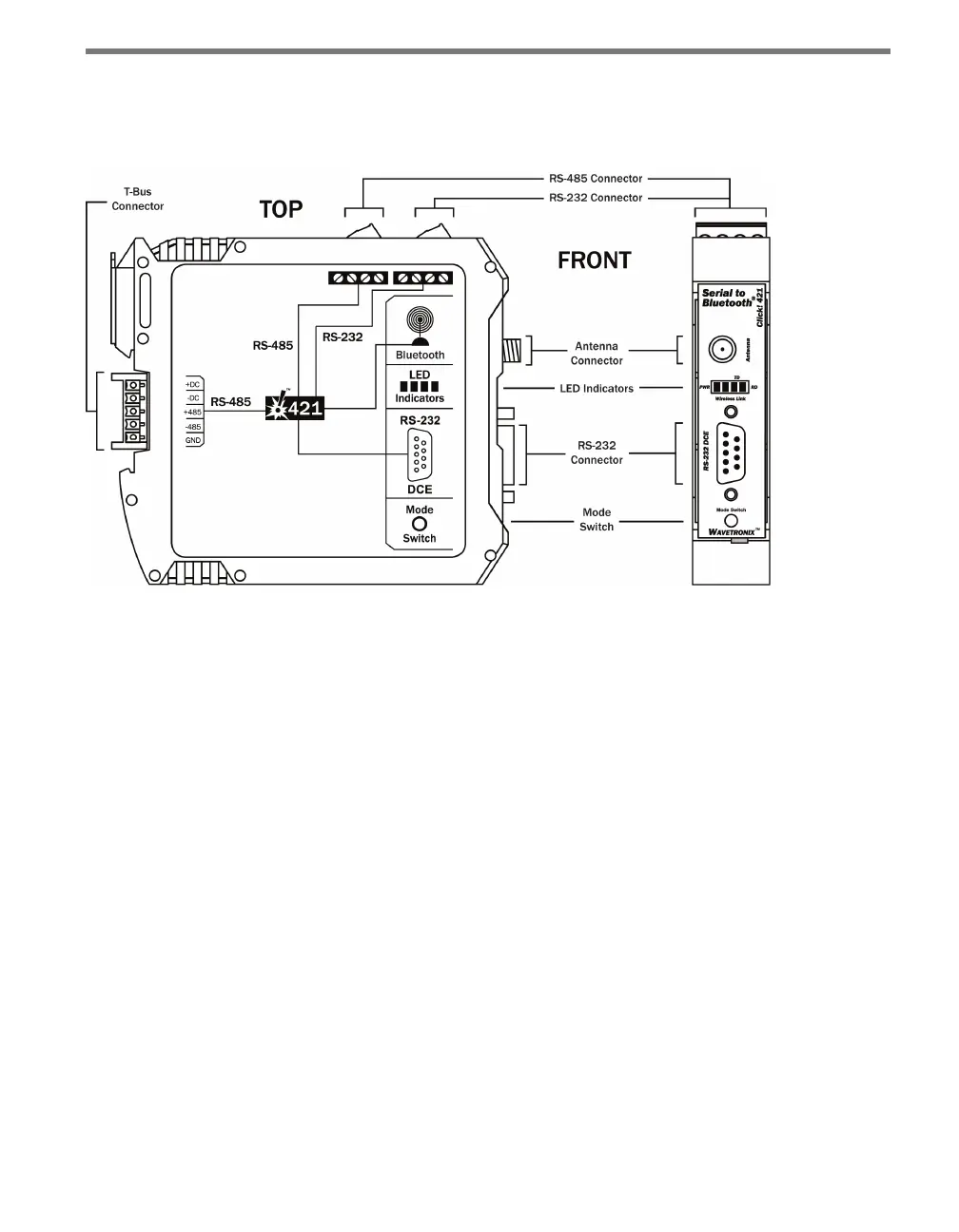
e Click 421 has several communication ports, plus features for conguration.
Figure 28.2 – Diagram of the Click 421
Communication Ports
e back of the Click 421 features a 5-position connector that plugs into a T-bus connector
and provides power and RS-485 communication to the device. It also passes that RS-485
communication to all other devices on the T-bus.
e top of the device has two pluggable screw terminal blocks. e rst block features -485,
+485 and two ground screw terminals for wiring RS-485 communication. (It will not be
necessary, however, to wire RS-485 through the screw terminal block if the device is con-
nected to a T-bus with uninterrupted RS-485 communication.) e second block features
RTS, CTS, TD and RD screw terminals for RS-232 communication. Both of these screw
terminal blocks can be removed for easy preinstallation wiring.
e front of the Click 421 features a DB-9 connector for RS-232 communication. A straight-
through cable can be used to connect from this port to a computer so that the device can be
congured using Click Supervisor.
Any data on one port will be transmitted simultaneously on all other ports.
Antenna
e Click 421 has a reversed polarity SMA antenna connector. An external antenna can be