CHAPTER 4 CLICK 104 67
9 33–36
Table 8.2 – Click 104 Rotary Switch Channel Input Map Settings
To set the switch, insert a small screwdriver into the slot and twist until the arrow is pointed
at the desired number.
Front Panel Menu
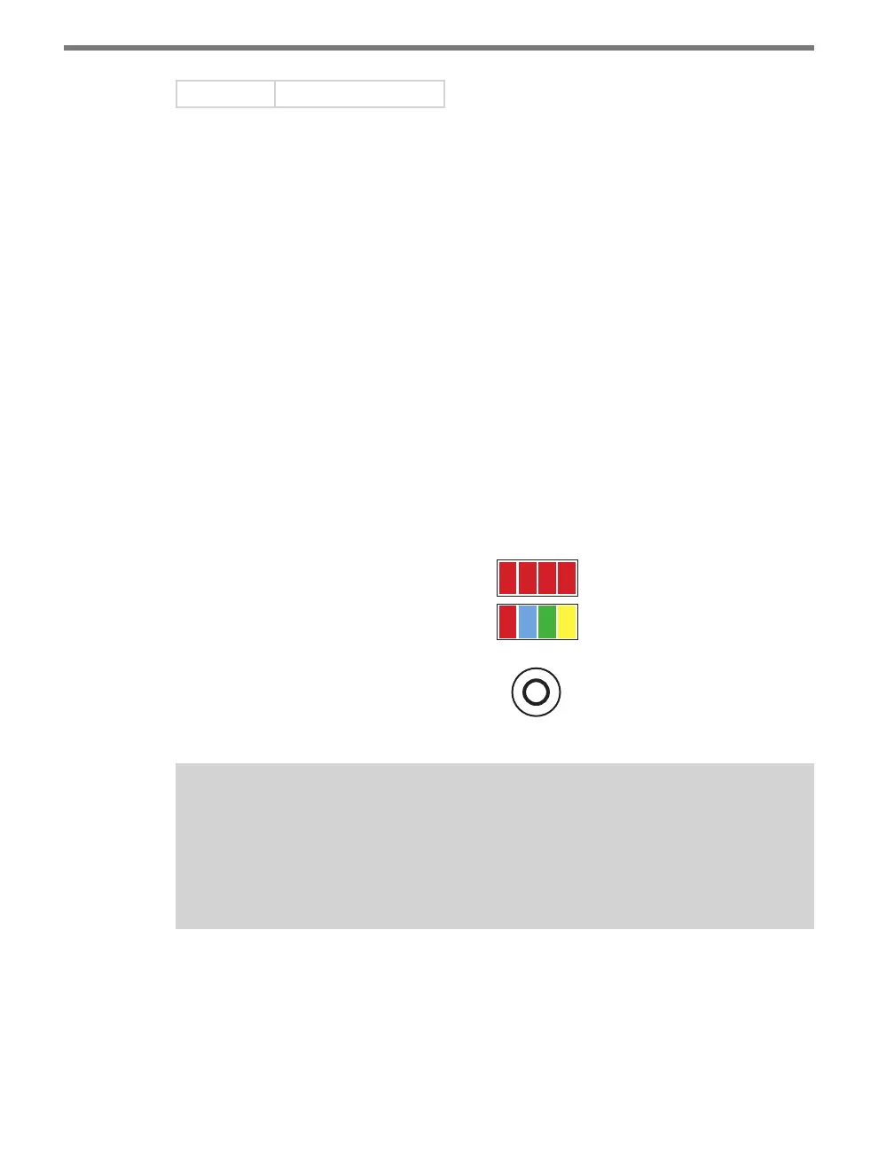
e front panel of the device features a push-button and three banks of LEDs for on-device
conguration and monitoring. e rst bank of LEDs, labeled Channel, displays the state of
the contact closure outputs and is described in the Physical Features section.
e two lower banks of LEDs, labeled Menu, and the push-button, labeled Mode Switch,
are used for navigating through Menu mode. is section will cover how to use the menu
to congure the Click 104.
e lower bank of LEDs will be referred to as Level 1 and is used in selecting menu options.
e upper bank will be referred to as Level 2 and is used in conguring the menu options.
Level 2 LEDs only light up when a menu selection is made using the Level 1 LEDs.
Mode Switch
Menu
PWR
OK TD RD
1 2 3 4
Level 1
Level 2
Figure 8.4 – Menu Indicator LEDs and Mode Switch
Note
The LEDs in the lower bank also function as activity/status indicators. These func-
tions, outlined in the Physical Features section of this chapter, are only executed
when the device is not in Menu mode. In this case, the upper bank of LEDs (Level 2)
remains o.
Navigating through the Menu
e mode switch push-button is used to enter Menu mode. To use the menu:
1 Press and hold the mode switch to enter Menu mode. e Level 1 LEDs will start to