4
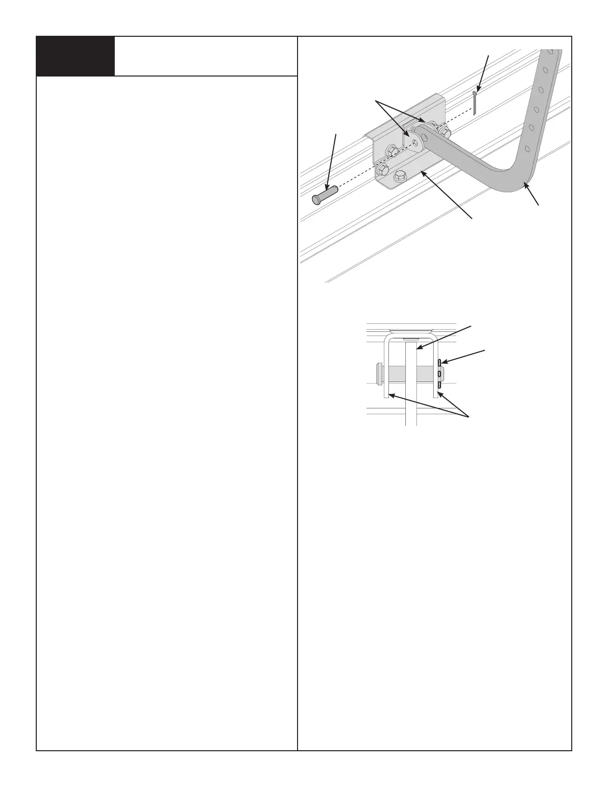
Align hole in the appropriate arm with holes in operator bracket
tabs, as shown in FIG. 5.1. Insert 5/16” x 1-1/4” clevis pin, mak-
ing sure hole in clevis pin is outside of second tab of operator
bracket. Insert hairpin cotter into clevis pin hole and spread hair-
pin cotter to ensure it will secure assembly, as shown in FIG. 5.2.
DOOR ARM ATTACHMENT
5
DOOR ARM
TOP VIEW
HAIRPIN
COTTER
OPERATOR
BRACKET
DOOR
ARM
HAIRPIN COTTER
(OUTSIDE OF OPERATOR
BRACKET TAB)
FIG. 5.1
FIG. 5.2
5/16” X 1-1/4”
CLEVIS PIN
OPERATOR
BRACKET TABS
OPERATOR BRACKET TABS
 Loading...