EasyManua.ls Logo

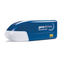
Wayne-Dalton Prodrive 3224C-Z User Manual

Wayne-Dalton Prodrive 3224C-Z
48 pages
To Next Page IconTo Next Page
Page #1 background imageLoading...
Page #1 background image
®
GARAGE DOOR OPENER
INSTALLATION INSTRUCTIONS AND OWNER’S MANUAL
Chain/ Belt Drive
Models: 3220C, 3221C, 3222C, 3224C, 3320B, 3322B, 3324B
3220C-Z, 3221C-Z, 3222C-Z, 3224C-Z, 3320B-Z, 3322B-Z, 3324B-Z
IMPORTANT NOTICE!
Read the enclosed instructions carefully before installing/operating
this garage door opener. Pay close attention to all warnings and
notes. This manual MUST be attached to the wall in close proximity
to the garage door.
Copyright 2008 Wayne-Dalton Corp. Part No. 325809 Rev.5 7/16/2008
FOR RESIDENTIAL SECTIONAL OVERHEAD GARAGE DOORS ONLY!
DO NOT USE ON ONE PIECE DOORS!
IMPORTANT! THE DOOR AND OPENER WILL NOT FUNCTION PROPERLY UNTIL
INFRARED SAFETY SENSORS ARE INSTALLED AND PROPERLY ADJUSTED!
GARAGE DOORS & OPENERS

Table of Contents

Question and Answer IconNeed help?

Do you have a question about the Wayne-Dalton Prodrive 3224C-Z and is the answer not in the manual?

Wayne-Dalton Prodrive 3224C-Z Specifications

General IconGeneral
Voltage120V
Frequency60 Hz
Horsepower1/2 HP
Wireless TechnologyZ-Wave
Maximum Door Weight500 lbs
Maximum Door Height8 ft
Remote Controls Included2
Battery BackupNo
DriveBelt
Speed7.5 inches per second
WarrantyLifetime (Motor), 1 Year (Other Parts)

Summary

Pre-Installation

Identify Your Door

Verify door type is sectional and with curved track; do not install on one-piece doors.

Test Your Door

Manually check door for smooth operation, balance, and no binding.

Attaching Opener to Rail

Aligning Drive Gear

Ensure proper engagement between the opener's drive gear and rail sprocket/cogs.

Securing Rail to Opener

Fasten the rail assembly to the opener unit using specified bolts.

Positioning Front Wall Bracket

Reinforce Header Wall

Strengthen the wall above the door opening for secure bracket mounting.

Positioning Motor End of Opener

Mounting Opener End

Secure to Ceiling Joists

Attach the opener rail assembly to ceiling joists using perforated angles.

Mounting Door Bracket

Wired Infrared Safety Sensor Installation

Sensor Placement and Alignment

Mount both sensor brackets at the same height and align sensors for beam integrity.

Connecting Safety Sensors to Opener

Wire Connections

Connect the sensor wires to the opener's terminal screws, observing polarity.

Setting Trolley Close Position

Setting Door Opening Travel

Determine Natural Open Position

Manually find the door's natural resting open position for setting the limit.

Obstruction Tests

Contact Obstruction Test

Verifies the door reverses on contact with a 1.5-inch object on the floor.

Safety Sensor Obstruction Test

Checks if safety sensors stop or reverse the door when obstructed.

Important Safety Instructions

HomeLink® Programming

Key Adjustments

Opening and Closing Force

Adjusts the force used for opening and closing to ensure safety.

Contact Obstruction Sensing

Fine-tunes the sensitivity of the closing obstruction reversal feature.

Programming Transmitters and Wall Stations

Related product manuals