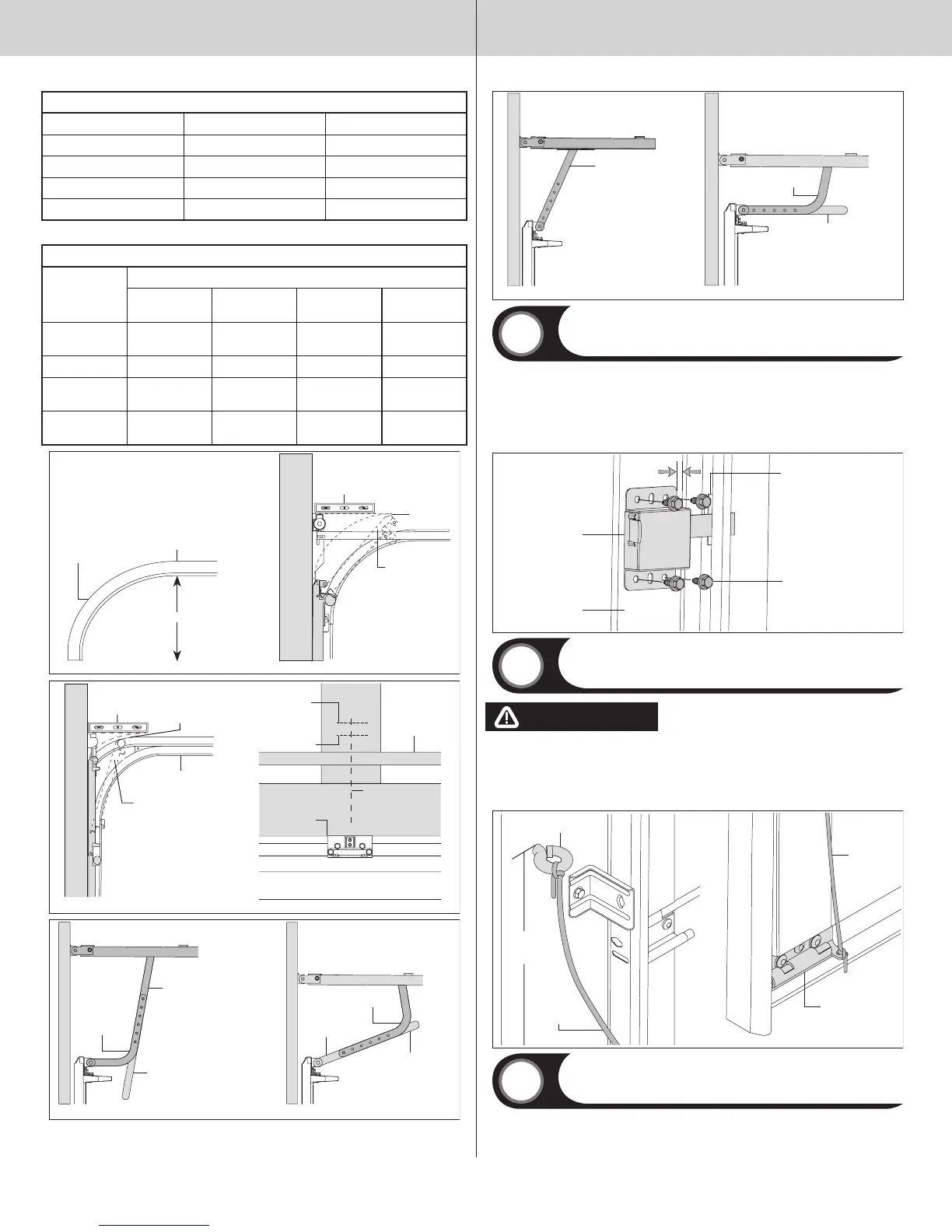
DRAWBAR OPERATOR HOOK-UP CHART,STANDARD LIFT FOR 12” AND 15” RADIUS
OPERATOR MODELS TYPE OF ARM BEING USED REF. ILLUSTRATIONS
QUANTUM/CLASSIC CURVED / STRAIGHT FIG 6
LINEAR STRAIGHT / CURVED FIG 5
LIFTMASTER (SEARS) CURVED / STRAIGHT FIG 6
GENIE CURVED / STRAIGHT FIG 6 Or FIG 5
DRAWBAR OPERATOR HOOK-UP CHART FOR LOW HEADROOM
OPERATOR
MODELS
TYPE OF ARM BEING USED
PREFERRED
HOOKUP
REF. ILLUSTRA-
TIONS
OPTIONAL
HOOK-UP
REF. ILLUSTRA-
TIONS
QUANTUM /
CLSSSIC
CURVED /
STRAIGHT
FIG. 8 STRAIGHT FIG. 7
LINEAR STRAIGHT FIG. 7 N/A N/A
LIFTMASTER
(SEARS)
CURVED /
STRAIGHT
FIG. 8 STRAIGHT FIG. 7
GENIE CURVED /
STRAIGHT
FIG. 8 STRAIGHT FIG. 7
FIG 1
12” or 15”
FIG 2
Horizontal
track
Level
High arc
Top section
Horizontal
radius
High arc
FIG 4FIG 3
TorqueMaster
®
counterbalance
Vertical
center line
From step
Typical 1/2”-1”
above high arc
High arc line
Header
Top section
Low headroom track
Level
Cut straight arm to
accomplish trolley
setting
FIG 6
FIG 5
Curved arm
Curved arm
Cut straight arm to
accomplish trolley
setting
Straight arm
Straight arm
Curved arm
Straight arm
FIG 8
FIG 7
Cut straight arm to
accomplish trolley setting
Inside Lock
Tools: Power drill, 7/16” Socket driver, Tape measure
Install the inside lock on the second section of the door. Secure the lock to the section with (4)
1/4”-20 x 11/16” self drilling screws. Square the lock assembly with the door section, and align
with the square hole in the vertical track. The inside lock should be spaced approximately 1/8”
away from the section edge.
IMPORTANT: INSIDE LOCK(S) MUST BE REMOVED OR MADE INOPERATIVE IN THE UNLOCKED
POSITION IF AN OPERATOR IS INSTALLED ON THIS DOOR.
Second section 1/8”
Inside lock
End cap
(4) 1/4”-20 x 11/16”
Self drilling screws
Square hole in
vertical track
Pull Down Rope
Tools: Power drill, 1/8” Drill bit, Tape measure
WARNING WARNING
DO NOT INSTALL PULL DOWN ROPE ON DOORS WITH OPERATORS. CHILDREN
MAY BECOME ENTANGLED IN THE ROPE CAUSING SEVERE OR FATAL INJURY.
Measure and mark the jamb approximately 48” to 50” (1220 to 1270 mm) from floor on the
right or left side of jamb. Drill 1/8” pilot hole for no. 6 screw eye. Tie the pull down rope to the
no. 6 screw eye and to the bottom corner bracket, as shown.
Bottom corner
bracket
Pull down
rope
No. 6 Screw eye
Pull down
rope
48” to 50”
From floor
Step Plate
Tools: Tape measure, Power drill, 7/16” Drill bit, 7/16” Wrench, Phillips
head screwdriver
Make one mark 1” (25 mm) up from the center of bottom edge of the bottom section and
another mark 2-3/16” (56 mm) up from the first mark.
NOTE: Top of step plate can be no higher than 8” from the bottom of the door.
Drill a 7/16” (11 mm) hole through the section at each mark and insert the outside step plate.
16
Please Do Not Return This Product To The Store. Contact your local Wayne-Dalton dealer. To find your local Wayne-Dalton dealer,
refer to your local yellow pages business listings or go to the Find a Dealer section online at www.Wayne-Dalton.com
 Loading...