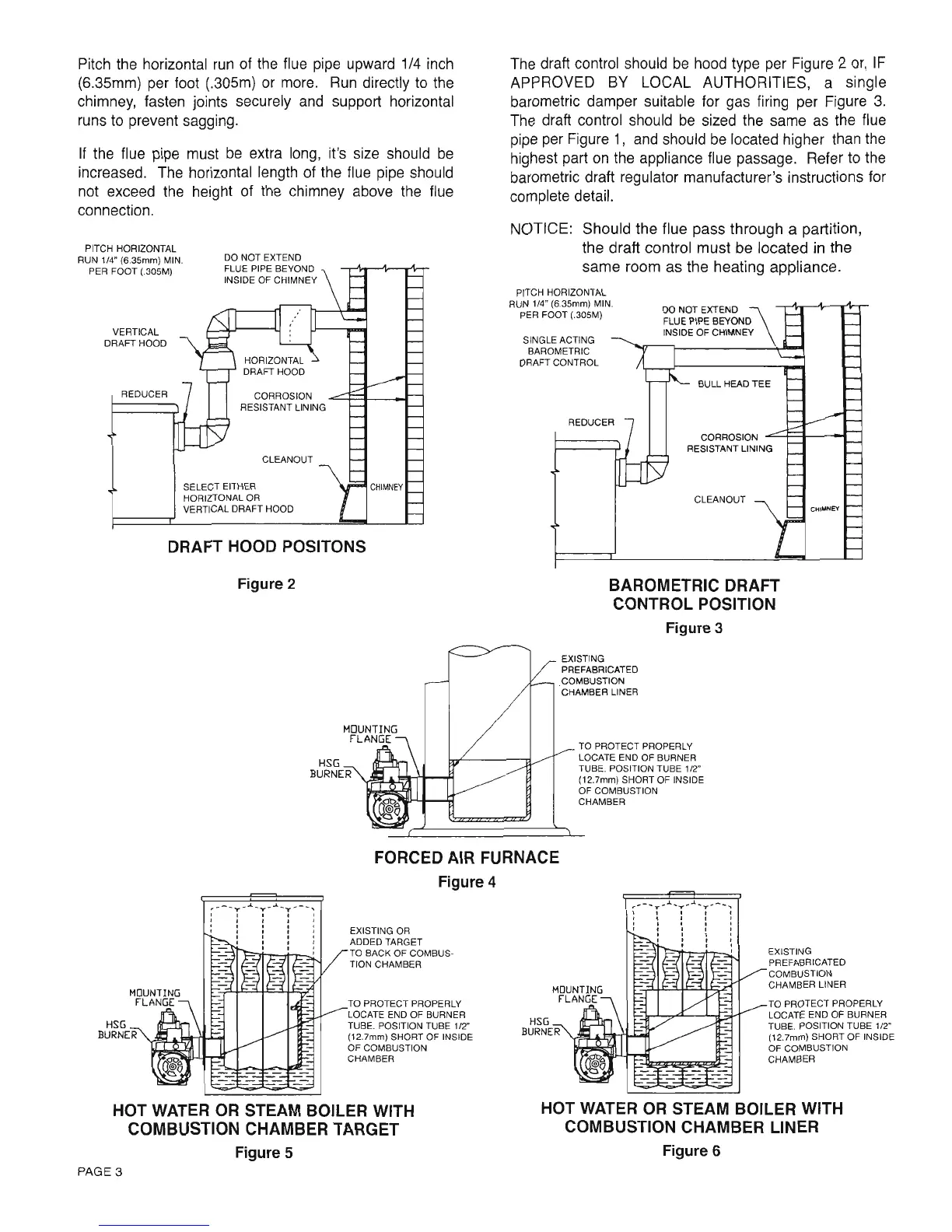
Pitch
the horizontal run
of the
flue
pipe
upward 1/4 inch
(6.35mm) per
foot
(.305m)
or more. Run directly
to the
chimney, fasten
joints
securely and
support horizontal
runs
to
prevent
sagging.
lf the
flue
pipe
must be
extra
long,
it's
size should be
increased. The
horizontal length
of the flue
pipe
should
not
exceed the height
of the chimney
above the flue
connection.
PITCH
HOBIZONTAL
RUN
1/4"
(6.35mm)
MlN.
PER FOOT
(.gosM)
VERTICAL
DRAFT HOOD
Figure
2
HSG
-
BURNER
The
draft control
should be
hood
type
per
Figure
2 or,lF
APPROVED
BY LOCAL AUTHORITIES,
a single
barometric damper
suitable
for
gas
firing
per
Figure
3.
The
draft control
should be sized the
same as the
flue
pipe
per
Figure 1,
and should be located higher
than the
highest
part
on the appliance flue
passage.
Refer
to the
barometric draft regulator manufacturer's
instructions for
complete detail.
NOTICE:
Should the flue
pass
through a
partition,
the draft control must
be
located
in the
same
room
as
the
heating
appliance.
PITCH HORIZONTAL
BUN 1/4"
(6.3smm)
MlN.
PEF FOOT
(.3osrV)
DO NOT EXTEND
FLUE PIPE
BEYONO
INSIDE
OF CHIMNEY
SINGLE
ACTING
BAROMETRIC
DRAFT CONTROL
BAROMETRIC
DRAFT
CONTROL POSITION
Figure
3
EXISTING
PREFABRICATEO
COMBUSTION
CHAMBEB
LINER
TO PROTECT PROPERLY
LOCATE END OF BURNEF
TUBE. POSITION TUBE
1/2'
(12.7mm)
SHORT OF INSIDE
OF COMBUSTION
CHAMBEB
FORCED
AIR FURNACE
Figure
4
EXISTING
OR
ADDED TARGET
TO BACK
OF COMBUS-
TION
CHAMBER
TO PROTECT
PBOPERLY
LOCATE END
OF BURNER
TUBE. POSITION
TUBE 1/2'
(12.7mm)
SHORT OF INSIDE
OF COMBUSTION
CHAI\4BER
EXISTING
PREFABRICATEO
COMBUSTION
CHAIV]BEB LINEFI
TO PROTECT PROPERLY
LOCATE END
OF
BURNEF
TUBE. POSITION TUBE 1/2"
(12.7mm)
SHOBT OF INSIDE
OF COMBUSTION
CHAMBEF
HOT
WATER
OR STEAM BOILER
WITH
COMBUSTION
CHAMBER
TARGET
Figure
5
PAGE
3
HOT WATER
OR STEAM BOILER
WITH
COMBUSTION
CHAMBER LINER
COFFOSION
RESISTANT
LINING
CLEANOUT
SELECT EITHER
HORIZTONAL
OR
VEFTICAL
DBAFT HOOD
DRAFT
HOOD POSITONS
Figure 6
Pitch
the
horizontal
run
of
the
flue
pipe
upward
1/4
inch
(6.35mm) per foot (.305m)
or
more.
Run
directly
to
the
chimney, fasten joints securely
and
support horizontal
runs
to
prevent sagging.
If
the flue pipe must
be
extra
long,
it's size should
be
increased. The horizontal length of the flue
pipe
should
not exceed
the
height of
the
chimney above
the
flue
connection.
CHI""NEY
CLEANOUT
BULL HEAD
TEE
CORROSION -=-+--1------'"
RESISTANT LINING
DO
NOT EXTEND
FLUE PIPE BEYOND
INSIDE OF CHIMNEY
SINGLE ACTING
BAROMETRIC
DRAFT CONTROL
The draft control should
be
hood type per Figure 2
or,
IF
APPROVED
BY
LOCAL AUTHORITIES, a single
barometric damper suitable for gas firing per Figure
3.
The
draft control should
be
sized the same
as
the flue
pipe
per Figure
1,
and
should
be
located higher than
the
highest part
on
the
appliance flue passage. Refer
to
the
barometric draft regulator manufacturer's instructions for
complete detail.
NOTICE: Should the flue pass through a partition,
the draft control must be located
in
the
same room as the heating appliance.
PITCH HORIZONTAL
RUN 1/4" (6.35mm) MIN.
PER FOOT (.305M)
CHIMNEY
CORROSION
RESISTANT LINING
CLEANOUT
DO NOT EXTEND
FLUE PIPE BEYOND
INSIDE
OF
CHIMNEY
SELECT EITHER
HORIZTONAL OR
VERTICAL DRAFT HOOD
DRAFT HOOD POSITONS
REDUCER
VERTICAL
DRAFT HOOD
PITCH HORIZONTAL
RUN 1/4" (6.35mm) MIN.
PER FOOT (.305M)
Figure 2
BAROMETRIC DRAFT
CONTROL POSITION
Figure 3
EXISTING
PREFABRICATED
COMBUSTION
CHAMBER LINER
HSG
BURNER
TO PROTECT PROPERLY
LOCATE END OF BURNER
TUBE. POSITION TUBE
112"
(12.7mm) SHORT OF INSIDE
OF COMBUSTION
CHAMBER
FORCED AIR FURNACE
Figure 4
HOT WATER
OR
STEAM BOILER WITH
COMBUSTION CHAMBER LINER
Figure 6
EXISTING
PREFABRICATED
COMBUSTION
CHAMBER LINER
TO PROTECT PROPERLY
LOCATE END OF BURNER
TUBE. POSITION TUBE 1/2"
(12.7mm) SHORT OF INSIDE
OF
COMBUSTION
CHAMBER
,,_
...
y
..
..l
..
.,.. .. .J.
...
y
..
__
, , ,
. , ,
,
, ,
. , ,
, , ,
, . ,
. ,
HSG
BURNER
EXISTING OR
ADDED TARGET
TO BACK OF COMBUS·
TION CHAMBER
TO PROTECT PROPERLY
LOCATE END OF BURNER
TUBE. POSITION TUBE 1/2"
(12.7mm) SHORT OF INSIDE
OF COMBUSTION
CHAMBER
HOT WATER OR STEAM BOILER WITH
COMBUSTION CHAMBER TARGET
Figure 5
PAGE 3
 Loading...


