SECTION
III
OPERATION
AND TROUBLESHOOTING
SEQUENCE OF OPERATION
- HSG
SERIES
POWER GAS
CONVERSION
BURNER
UTILIZING
HONEYWELL
S89F
GAS
PRIMARY P/N
62759-002
WBUILT IN
30 SECOND PREPURGE
On
a call
for
heat,
voltage
(24V)
is applied to motor start
relay and air
switch. Once
the fan motor reaches
operating
rpm
combustion air
pressure
is
sensed
by the
air
proving
switch
and closes the
switch
contacts
energizing the S89F
gas primary
control.
THE S89F
gas
primary
control
has
an
internal
30
second
prepurge
timer.
After the
initial
30 second
prepurge,
an internal 8
second safe start
check of the
S89F
will commence.
Once
this is
successfully
completed, the
S89F simultaneously energizes the
gas
valve
and
ignition
transformer. Gas flows and the
transformer
produces
an approximate 7300 volt spark
end
point
grounded
at the burner head establishing
main burner flame.
At the
start of each
heat
cycle, there
is
a trial
for ignition
period
of four
(4)
seconds duration. Normally, burner
flame will be established
before the end of this
period.
Once the flame is established,
sparking
will cease and
the flame rod
will
provide
flame monitoring to the
S89F
gas
control
primary
for
the
remainder
of the
heat
cycle.
lf the flame should be extinguished during the heat
cycle, the S89F
gas
control
primary
will
go
into
the 30
second
prepurge
and
8 second
safe start check, then
re-energize the
gas
valve and ignition transformer in an
attempt to establish the main burner flame. lf this
does
not occur within the 4
second
trial for ignition
period,
the
S89F
gas
primary
control
will
go
into lockout de-
energizing the
gas
valve and ignition transformer.
To restart
the system, the main
power
or thermostat
must be de-energized momentarily, then re-energized.
lf
at any time
during
the
heat
cycle, there is an
insufficient
supply
of combustion
air
to
the burner, the
air switch
will
open,
putting
the
system
into lockout
closing the
gas
valve.
BURN ER
GAS PRIMARY
HSG POWER GAS
WITH HONEYWELL
S89F
24VAC
TRANS.
N
WIRE
NUT
BURNER GND
24VAC
YL-__--1--l
t<l
YL--------lJl
REOUNOANT
GAS
VALVE
IGNITION ROD
IF
ANY OF IHE ORIGIML WIRE.
AS
SUPPUEO $TH THE APPLINCE,
MUST
8E
REPLACED. IT VUSI
EE
REPLACED Y{ITH TYPE AWM ISGA
IO5'C WIRE
OR EOUIVALENT.
PAGE 9
lScHEMATiel
SECTION III
OPERATION AND TROUBLESHOOTING
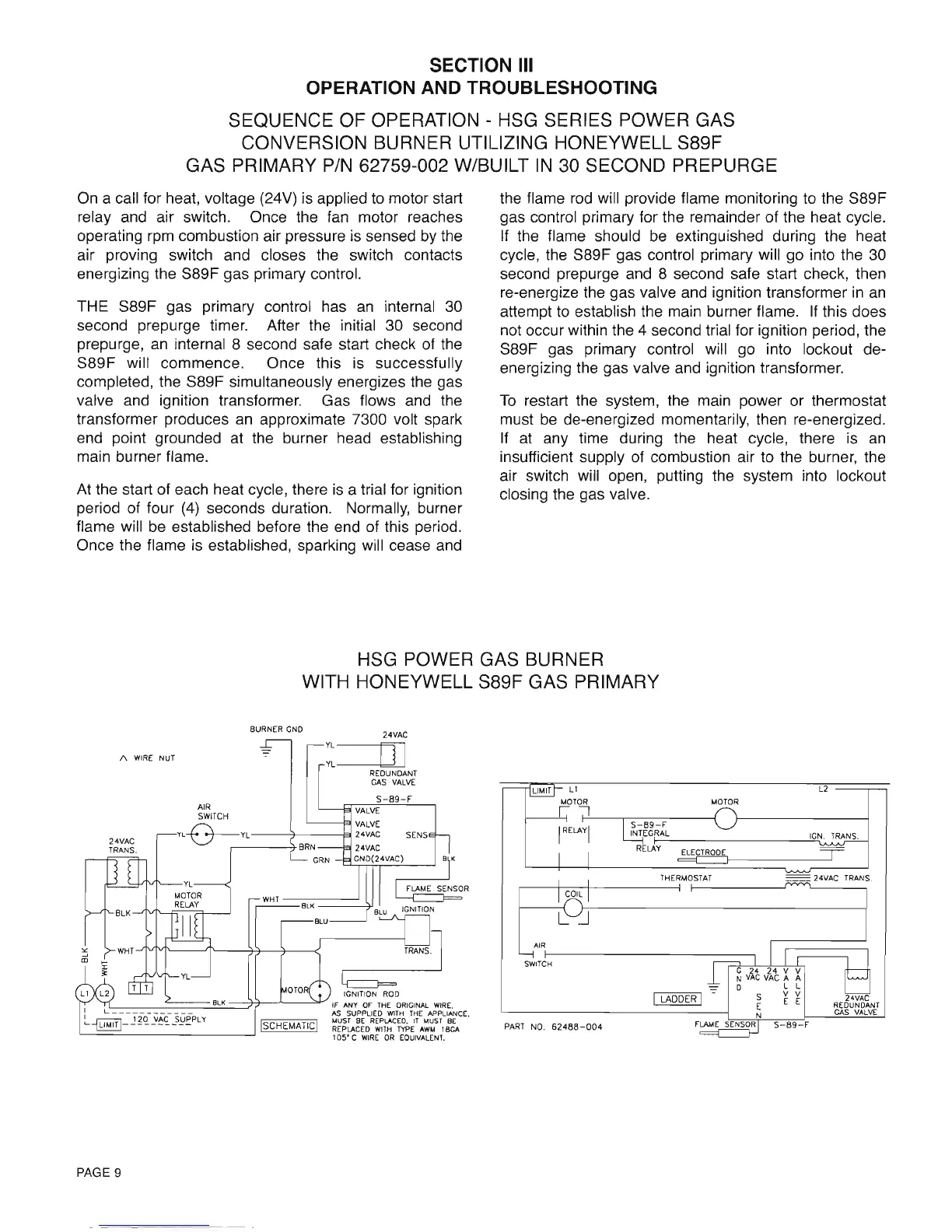
SEQUENCE OF OPERATION - HSG SERIES POWER GAS
CONVERSION BURNER UTILIZING HONEYWELL S89F
GAS PRIMARY
PIN
62759-002 W/BUILT
IN
30 SECOND PREPURGE
On a call for heat, voltage (24V) is applied
to
motor start
relay and air switch. Once the
fan
motor reaches
operating rpm combustion air pressure is sensed by the
air proving switch and closes the switch contacts
energizing the S89F gas primary control.
THE S89F gas primary control has
an
internal 30
second prepurge timer. After the initial 30 second
prepurge,
an
internal 8 second safe start check of the
S89F will commence. Once this is successfully
completed, the S89F simultaneously energizes the gas
valve and ignition transformer. Gas flows and the
transformer produces
an
approximate 7300 volt spark
end point grounded at the burner head establishing
main burner flame.
At
the start of each heat cycle, there
is
a trial for ignition
period of four
(4)
seconds duration. Normally, burner
flame will
be
established before the end of this period.
Once the flame is established, sparking will cease and
the flame
rod
will provide flame monitoring to the S89F
gas control primary for the remainder of the heat cycle.
If
the flame should be extinguished during the heat
cycle, the S89F gas control primary will go into the 30
second prepurge and 8 second safe start check, then
re-energize the gas valve and ignition transformer
in
an
attempt
to
establish the main burner flame.
If
this does
not occur within the 4 second trial for ignition period, the
S89F gas primary control will go into lockout de-
energizing the gas valve and ignition transformer.
To
restart the system, the main power or thermostat
must
be
de-energized momentarily, then re-energized.
If
at
any time during the heat cycle, there is
an
insufficient supply of combustion air to the burner, the
air switch will open, putting the system into lockout
closing the gas valve.
HSG POWER GAS BURNER
WITH HONEYWELL S89F GAS PRIMARY
~.L1
L2
MOTOR
MOTOR
~-:l
~9-F
I
RELAYI
INTEGRAL
IGN.
TRANS.
RELAY
~
I I
~
I I
THERMOSTAT
~
24VAC
TRANS.
I
COIL
I
L..::J
AIR
~~
II
~
SWITCH
1 G 24
24
V V
N
VAC
VAG
A A
= 0 L L
I
LADDER
I
-
S
V
V
E
E E
REDUNDANT
N
GAS
VALVE
PART
NO.
62488-004
FLAME
SENSOR
I
S-B9-F
24VAC
YL
--------r=n
YL-------UJ
REDUNDANT
GAS
VALVE
S-89-F
8w
BURNER
GND
~~'TCH
VALVE
~
VALVE
YL~YL----;}-----F1
24VAC SENS
,------'1-BRN
24VAC
GRN
GNO(24VAC~8
K
FLAME
SENSOR
WHT
==S;:"K"====-~
BLK
BLU
IGNITION
1\
WIRE
NUT
24VAC
TRANS.
IGNITION
ROO
:e-
__
---===~8L~K
=7(I---'-----"'v::s
A;~P~~E6H~?HRI~~~
APW~~I~CE,
MUST
BE
REPLACED.
IT
MUST
BE
REPLACED
WITH
TYPE
AWM
18CA
105"
C
WIRE
OR
EQUIVALENT.
ISCHEMATlcl
'-----==---
---.J
PAGE 9
 Loading...


