G. ELECTRICAL
The installation must
be
wired
and GROUNDED
in
accordance
with local
codes or
in their
absence,
with
the
National
Electric Code ANSI/NFPA No. 70-
1987
or
latest
edition.
For
the 120 VAC wiring
to
the burner,
use solid
copper conductor wire not lighter than #14 AWG. lf
a
fused
disconnect
is
used, it should be
fused
for a
minimum
of
15
amps.
CAUTION:
Each installation must include
suitable
limit controls. Existing oil burner
combination limit
and operating controls are normally
not
suitable
for
gas
burner use.
CAUTION:
The burner is
equipped
with it's own 24
VAC
transformer. Do
not
add any
24 VAC
power
consuming device in
the
24 VAC control
circuit of
the burner, as it could overload the transformer.
Set
the room thermostat
"heat
anticipator" for the
totaf current draw of the 24
VAC
burner operation
circuit.
(HSG200
0.55 amps,
HSG400
0.7 amps)
GAUTION:
Label
all
wires
orior
to disconnection
when
servicing controls. Wiring errors can cause
improper and dangerous operation.
Verify
proper
operation after
servicing.
NOTE: lf
any of
the
original burner
wiring must
be
replaced, it must
be
replaced with #18
AWG 105 degrees
C
wire or equivalent.
Section 3- Operation and
Troubleshooting for
applicable burner wiring diagrams.
H. MAIN
BURNER
ORIFICE SIZING
AND INSTALLATION
The HSG200 and HSG400
power gas
conversion
burners are approved for use with natural
and
propane
gas
only.
The HSG200 and HSG400
burner
models
are
shipped
labeled
and orificed for natural
gas.
To
conveft to
propane gas
and/or increase BTU/HR
(kcal/Hr)
input on natural or
propane
gas,
an
orifice
kit is
supplied
with
each burner
with the
orifices
shown
in Figure
10.
When selecting a desired BTU/HR
(kcal/Hr)
input,
figure 140,000 BTU's
per
gallon
of
oil input. For
example:
furnace or
boiler
rating
of 0.75gph at
100
psig.
The
0.75 x
140,000
=
105,000
BTU's input
rate. lt may be
possible
to reduce the firing rate on
natural
or
propane gas
15%
lo
20o/",
as
most
older
appliances are oversized for the heating load.
(2.83875L
x 9356 kcal
=
26559.35 kcal)
To
remove
or
interchange main
orifice discs
refer
to
Figure 15
(Page
16).
1. Remove slotted orifice cap,
ltem #40, making
sure orifice
cap
gasket,
#39,
stays
attached to
orifice cap and
is not
damaged.
2. Remove orifice
spring,
ltem #38, to access
and
remove orifice disc. ltem #42.
3.
Install desired orifice from Figure 10, making
sure
it is
seated
flat in
the orifice
holder,
ltem
#37.
4. Replace orifice
spring and securely tighten
orifice cap against orifice cap
gasket
in orifice
holder.
NOTE: For
50 cycle
application
derate input
by
15%
HSG
SERIES
POWER
GAS
CONVERSION BURNERS
ORIFICE CHART
Figure
10
ORIFICE
SIZE & DRILL
MANIFOLD PRESSURE
2.0"
(498.2Pa)
3.0"
(747.3Pa)
4.0"
(996.4Pa)
HSG2OO NATURAL
GAS
#29 - .136
(3.4544mm)
50.000 BTU
(52750kJ)
64.000 BTU {67520kJ)
76.500 BTU
(80707.5kJ
#8 - .199
(5.0546mm)
i4,000
BTU
(78070kJ)
95.000 BTU
(100225kJ)
116.000 BTU
(122380kJ
J
-
.277
(7.0358mm)
112.000 BTU
(118160kJ)
138.000 BTU
(145590kJ)
164.000
BTU
(173020kJ
Q
-
.332
(8.4328mm)
160,000 BTU
(168800kJ)
206,000
BTU
(217330kJ)
HSG2OO L.P.
GAS
#30 - 128
(3.2512mm)
49.000 BTU
(5169skJ)
58.500 BTU
(61717.5kJ)
68.200 BTU
(71951kJ)
#27 -
j44
(3.6576mm)
66.000 BTU
(69630kJ)
78,000
BTU
(82290kJ)
92.000 BTU
{97060kJ)
#15
-.180
(4.572mm)
82.000 BTU
(86510kJ)
'1
12.500 BTU
(1
1 8687.5kJ)136.000 BTtl
(143480kJ)
D
-
.246
(6.2484mm)
131,000 BTU
(138205kJ)
1 87.500 BTU
(1
9781
2.5kJ)243,000 BTU
(256365kJ)
HSG4OO NATURAL
GAS
T
-
.358
(9.0932mm)
200.000 BTU
(211000kJ)
248.000 BTU
(261640kJ)
285000 BTU
(300675kJ)
15/32 -
.468
(11.8872mm)
265,000
BTU
(279575kJ)
343.000 BTU
{361865kJ)
400,000 BTU
(422000kJ)
HSG4OO L.P.
GAS
K - .281
(7.1374mm)
190.000
BTU
(200450kJ)
242.500 BTU
(255837.5kJ
)
295.000
BTU {311225kJ)
0-
.332
(8.4328mm)
242,500 BTU
(255837kJ)
332,500 BTU
(350787.5kJ)
400,000
BTU
(422000kJ)
PAGE
5
G.
ELECTRICAL
The installation must be wired and GROUNDED
in
accordance with local codes or
in
their absence,
with the National Electric Code ANSI/NFPA
No.
70-
1987 or latest edition.
For the 120
VAC
wiring
to
the burner, use solid
copper conductor wire not lighter than #14 AWG.
If
a fused disconnect is used, it should
be
fused for a
minimum of 15 amps.
CAUTION: Each installation must include suitable
limit controls. Existing oil burner combination limit
and operating controls are normally not suitable for
gas burner use.
CAUTION: The burner is equipped with it's own 24
VAC
transformer.
Do
not add any 24
VAC
power
consuming device
in
the 24
VAC
control circuit of
the burner, as
it
could overload the transformer.
Set the room thermostat "heat anticipator" for the
total current draw of the 24
VAC
burner operation
circuit. (HSG200 0.55 amps, HSG400 0.7 amps)
CAUTION: Label
all
wires prior to disconnection
when servicing controls. Wiring errors can cause
improper and dangerous operation.
Verify proper operation after servicing.
NOTE: If any of the original burner wiring must
be
replaced, it must
be
replaced with #18
AWG 105 degrees C wire or equivalent.
Section 3- Operation and Troubleshooting for
applicable burner wiring diagrams.
H.
MAIN BURNER ORIFICE SIZING
AND INSTALLATION
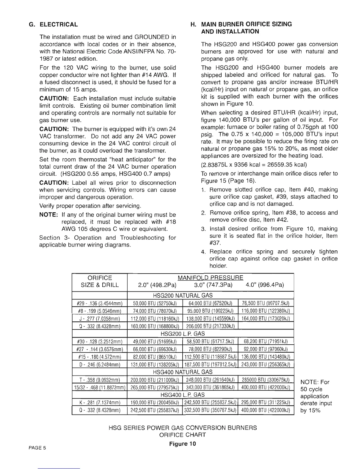
The HSG200 and HSG400 power gas conversion
burners are approved for use with natural and
propane gas only.
The HSG200 and HSG400 burner models are
shipped labeled and orificed for natural gas.
To
convert to propane gas and/or increase BTU/HR
(kcal/Hr) input
on
natural or propane gas,
an
orifice
kit
is
supplied with each burner with the orifices
shown
in
Figure 10.
When selecting a desired BTU/HR (kcal/Hr) input,
figure 140,000 BTU's per gallon of oil input. For
example: furnace or boiler rating of 0.75gph at 100
psig. The 0.75 x 140,000
==
105,000 BTU's input
rate.
It
may
be
possible to reduce the firing rate
on
natural or propane gas 15%
to
20%, as most older
appliances are oversized for the heating load.
(2.83875L x 9356 kcal
==
26559.35 kcal)
To
remove or interchange main orifice discs refer
to
Figure 15 (Page 16).
1.
Remove slotted orifice cap, Item #40, making
sure orifice cap gasket, #39, stays attached to
orifice cap and is not damaged.
2.
Remove orifice spring, Item #38,
to
access and
remove orifice disc, Item #42.
3.
Install desired orifice from Figure 10, making
sure
it
is
seated flat
in
the orifice holder, Item
#37.
4.
Replace orifice spring and securely tighten
orifice cap against orifice cap gasket
in
orifice
holder.
PAGE 5
ORIFICE
MANIFOLD PRESSURE
SIZE
& DRILL
2.0" (498.2Pa) 3.0" (747.3Pa)
4.0" (996.4Pa)
HSG200
NATURAL
GAS
#29
-
.136
(3.4544mm)
50,000
BTU
152750kJl
64,000
BTU
167520kJ)
76
500
BTU
180707.5kJ)
#8
-
.199
(5.0546mml
74,000
BTU
178070kJ)
95,000
BTU
(1
00225kJ)
116,000
BTU
(122380kJ)
J-
.277
(7.0358mm)
112,000
BTU
(118160kJ)
138,000
BTU
1145590kJ)
164,000
BTU
1173020kJ)
Q -
.332
(8.4328mm)
160,000
BTU
1168800kJ)
206,000
BTU
(217330kJ)
HSG200
L.P.
GAS
#30
-
.128
13.2512mm)
49,000
BTU
151695kJ)
58,500
BTU
161717.5kJ)
68,200
BTU
171951
kJ)
#27
-
.144
(3.6576mm)
66,000
BTU
169630kJ)
78,000
BTU
182290kJ)
92,000
BTU
197060kJ)
#15
-
.180
14572mm)
82,000
BTU
186510kJ)
112,500
BTU
1118687.5kJ)
136,000
BTU
1143480kJ)
D·
.246
(6.2484mm)
131,000
BTU
1138205kJ)
187,500
BTU
(197812.5kJ)
243,000
BTU
1256365kJ)
HSG400
NATURAL
GAS
T-
.358
(9.0932mm)
200,000
BTU
(211
OOOkJl
248,000
BTU
1261640kJ)
285000
BTU
1300675kJ)
15/32
-
.468
(11.8872mm)
265,000
BTU
(279575kJ)
343,000
BTU
(361865kJ)
400,000
BTU
(422000kJl
HSG400
L.P.
GAS
K-
.281
(7.1374mm)
190,000
BTU
(200450kJ)
242,500
BTU
(255837.5kJ)
295,000
BTU
1311225kJl
Q -
.332
(8.4328mm)
242,500
BTU
(255837kJ)
332,500
BTU
(350787.5kJ)
400,000
BTU
(422000kJ)
HSG SERIES POWER GAS CONVERSION BURNERS
ORIFICE CHART
Figure
10
NOTE: For
50 cycle
application
derate input
by 15%
 Loading...


