E.
COMBUSTION
CHAMBER
A combustion chamber
is normally
required to
protect
non-heat
transfer surfaces, and to
provide
a
radiant
bed
for rapid heat transfer
to the
primary
surfaces of the
heat
exchanger.
lf in
good
condition,
the existing combustion chamber can be used.
Afull
combustion chamber
liner is recommended for
warm air
furnaces,
(see
Figure 4),
and a target
wall
or
full
combustion chamber liner is recommended
for wet leg cast
iron
or steel boilers.
(See
Figures 5
and 6). lf a built-up chamber is necessary, use
2300'
F
(1260"C)
minimum insulating fire-brick or
fiberfrax.
THE BURNER
AIR TUBE MUST
NOT BE
ALLOWED TO EXTEND INTO THE
CHAMBER
PROPER; lT MUST BE
SET
1/2 INCH
(12.7mm1
SHORT
OF
THE INSIDE SURFACE.
Before
permanently
securing the burner to the
heating appliance
with
either the adjustable mounting
flange or
pedestal
or cementing around the air tube
in the combustion chamber opening,
check
that the
burner
head
assembly
is free
of
foreign
materials and
that the
sensor
and electrode
probes
have not been
damaged or
repositioned,
see
Figure 13.
RECOMMENDED
COMBUSTION
CHAMBER SIZES
Figure 7
SUPPLY
LINE
CONNECTION
TO
BURNER
F.
GAS
PIPING
NOTICE:
All
piping
must comply
with
state
and/or
local
codes.
The
available
gas
supply
pressure
should
be within minimum and maximum
pressures
shown
in
the burner specifications.
lf
the
gas
supply
pressure
exceeds the 14"
W.C.
(3.5
k Pa)
maximum,
an
intermediate main
gas
regulator must
be installed
ahead of the main
gas
manual
shut
off valve
shown
in Figure 8.
WARNING: Failure
to
install
the
intermediate
gas
regulator will result in
gas
leakage from burner
gas
valve.
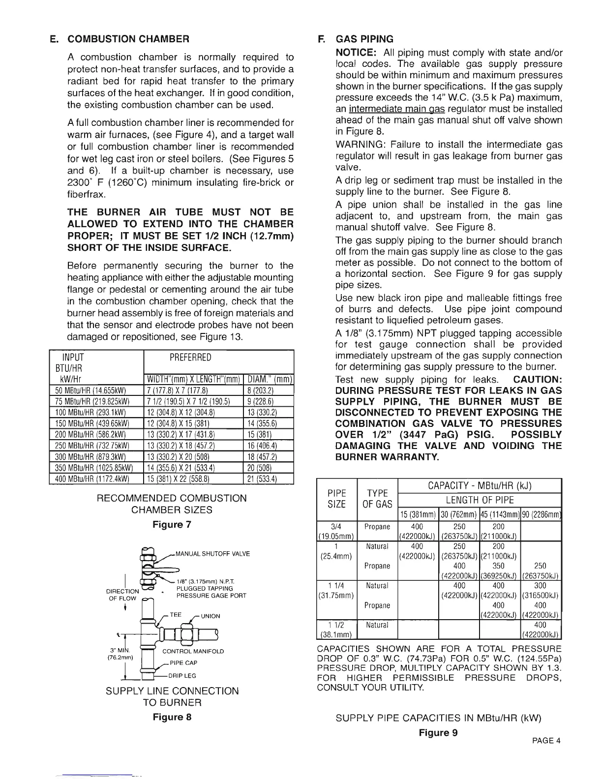
A drip leg
or sediment
trap must be installed in the
supply
line
to the burner. See
Figure
8.
A
pipe
union
shall be
installed in the
gas
line
adjacent to, and upstream from, the main
gas
manual
shutoff
valve,
See
Figure
8.
The
gas
supply
piping
to the burner
should
branch
off
from the main
gas
supply
line
as close to the
gas
meter as
possible.
Do not
connect to the bottom of
a
horizontal
section. See
Figure
9
for
gas
supply
pipe
sizes.
Use
new black iron
pipe
and malleable fittings free
of burrs and defects. Use
pipe
joint
compound
resistant to liquefied
petroleum gases.
A118"
(3.175mm)
NPT
plugged
tapping accessible
for test
gauge
connection shall be
provided
immediately upstream of the
gas
supply connection
for
determining
gas
supply
pressure
to the burner.
Test new
supply
piping
for leaks. CAUTION:
DURING PRESSURE TEST FOR LEAKS IN GAS
SUPPLY
PIPING, THE BURNER MUST BE
DISCONNECTED
TO
PREVENT
EXPOSING THE
COMBINATION
GAS VALVE TO PRESSURES
OVER 112"
(3447
PaG)
PSIG. POSSIBLY
DAMAGING THE VALVE AND VOIDING THE
BURNER WARRANTY.
CAPACITIES
SHOWN
ARE FOR A TOTAL PRESSURE
DROP OF 0.3" W.C.
(74.73Pa)
FOR
0.5"
W.C.
(12a.55Pa)
PRESSURE DROP. MULTIPLY CAPACITY SHOWN
BY 1.3.
FOR HIGHER PERMISSIBLE
PRESSURE DROPS,
CONSULT
YOUR
UTILITY.
SUPPLY
PIPE
CAPACITIES
lN MBtu/HR
(kW)
INPUT
BTU/HR
kWHr
PREFERRED
wlu I H"{mm) x LLNU I H"(mm)ulAM."
(mm
50 MBtu/HH
(.|4.655kW)
7 n77 8\X7 t177 8\ 8
(203.2)
75 MBtu/HR
(219.825kW)
7 1/2
(190
5) X 7 1/2
(190.5)
9 {228.6)
100 MBtu/HR
(293.1kW)
12
(304.8)
X 12
(304.8)
1
3
(330.2)
150 MBtu/HR
(439
65kW)
12
(304.8)
X 15
(381)
14
(355
6)
200 MBtu/HR
(586.2kW)
13
(330.2)
X 17
(431.8)
15
(381
)
250 MBtu/HR fi32.75kW)
13
(330.2)
X
18
1457.2)
'16
(406.4)
300 MBtu/HR f879,3kW) 13
(330.2)
X 20
(508)
18
U57.2\
350 MBtu/HR
(1
025.85kW)
14
(355.6)
X 21
(533.4)
20
(508)
400 MBtu/HR {11i2.4kw) t5
(381)
X 22 {558.8) 21
(533.4)
PI PE
SIZE
TYPE
OF GAS
CAPACITY -
MBtu/HR
(kJ)
LENGTH OF PIPE
15
(381mm)
l0
(762mm)
15
(1143mm
)0
(2286mm
3t4
t19.05mm)
Propane 400
422000k.t.|
250
t263750k,
200
21 1
000kJ)
1
(25.4mm)
l\atu ral
Propane
4UU
422000kJ)
z5u
(263750kJ
400
ta220nok.l
ZUU
21 1
000kJ)
350
i6q25nk. t)
250
'26i750k.t\
1 1t4
(31.75mm)
Natural
Propane
400
(422000kJ)
400
422000kJ)
400
422000k.1\
300
31 6500kJ)
400
422000kJ)
1 1t2
l38.1mm)
Natural
400
arrnnnk.t\
Figure
8
Figure
9
PAGE 4
PAGE 4
E.
COMBUSTION CHAMBER
A combustion chamber is normally required to
protect non-heat transfer surfaces, and to provide a
radiant bed for rapid heat transfer to the primary
surfaces of the heat exchanger.
If
in
good condition,
the existing combustion chamber can be used.
A full combustion chamber liner is recommended for
warm air furnaces, (see Figure 4), and a target wall
or
full combustion chamber liner is recommended
for wet leg cast iron
or
steel boilers. (See Figures 5
and 6). If a built-up chamber is necessary, use
2300° F (1260°C) minimum insulating fire-brick
or
fiberfrax.
THE BURNER AIR TUBE MUST NOT
BE
ALLOWED TO EXTEND INTO THE CHAMBER
PROPER; IT MUST
BE
SET 1/2 INCH (12.7mm)
SHORT OF THE INSIDE SURFACE.
Before permanently securing the burner to the
heating appliance with either the adjustable mounting
flange
or
pedestal or cementing around the air tube
in
the combustion chamber opening, check that the
burner head assembly is free of foreign materials and
that the sensor and electrode probes have not been
damaged
or
repositioned, see Figure 13.
INPUT
PREFERRED
BTU/HR
kW/Hr
WIDTH"(mm)
X
LENGTH"(mm)
DIAM."
(mm
50
MBtu/HR
(14655kW)
7
(177.8)
X7
(177.8)
8
(203.2)
75
MBtu/HR
(219825kW)
71/2
(1905)
X
71/2
(190.5)
9
(2286)
100
MBtu/HR
293,lkW)
12
304,8
X
12
304.8)
13
330.2)
150
MBtu/HR
43965kW)
12
304.8
X
15
381)
14
3556)
200
MBtu/HR
586,2kW)
13
330.2
X17
431.8)
15
381)
250
MBtu/HR
73275kW)
13
330.2
X
18
457.2)
16
4064)
300
MBtu/HR
8793kW)
13
330.2
X
20
508)
18
457.2)
350
MBtu/HR
102585kW)
14
355.6
X
21
5334)
20
508)
400
MBtu/HR
11724kW)
15
381)
X
22
(558.8)
21
5334)
RECOMMENDED COMBUSTION
CHAMBER SIZES
Figure 7
~
ANUALSHUTOFFVALVE
I 1/8" (3,175mm)
N.P.T.
DIRECTION • PLUGGED TAPPING
OF FLOW PRESSURE GAGE PORT
I
'i,--y--+-
PIPE CAP
DRIP LEG
SUPPLY LINE COI\II\IECTION
TO BURNER
Figure 8
F.
GAS PIPING
NOTICE:
All piping must comply with state
andlor
local codes. The available gas supply pressure
should be within minimum and maximum pressures
shown
in
the burner specifications. If the
gas
supply
pressure exceeds the 14" W.C. (3.5 k Pa) maximum,
an
intermediate main gas regulator must be installed
ahead of the main gas manual shut off valve shown
in
Figure
8.
WARNING: Failure to install the intermediate
gas
regulator will result
in
gas leakage from burner gas
valve.
A drip leg or sediment trap must be installed in the
supply line to the burner. See Figure
8.
A pipe union shall be installed
in
the gas line
adjacent to, and upstream from, the main gas
manual shutoff valve. See Figure
8.
The gas supply piping to the burner should branch
off from the main gas supply line as close to the gas
meter as possible. Do not connect to the bottom
of
a horizontal section. See Figure 9 for gas supply
pipe sizes.
Use new black iron pipe and malleable fittings free
of burrs and defects. Use pipe joint compound
resistant to liquefied petroleum gases.
A 1/8" (3.175mm) NPT plugged tapping accessible
for
test
gauge
connection
shall be
provided
immediately upstream of the gas supply connection
for determining gas supply pressure to the burner.
Test new supply piping for leaks.
CAUTION:
DURING PRESSURE TEST FOR LEAKS
IN
GAS
SUPPLY PIPING, THE BURNER
MUST
BE
DISCONNECTED TO PREVENT EXPOSING THE
COMBINATION GAS VALVE TO PRESSURES
OVER
1/2"
(3447
PaG) PSIG. POSSIBLY
DAMAGING THE VALVE AND VOIDING THE
BURNER WARRANTY.
PIPE
TYPE
CAPACITY
- MBtu/HR
(kJ)
SIZE
OF
GAS
LEI~GTH
OF
PIPE
15
(381mm)
30
(762mm)
45
(1143mm)
90
(2286mm
3/4
Propane
400
250 200
1(19.05mm)
422000kJ)
I
(263750kJ)
211000kJ)
1
Natural
400
250
200
(25.4mm)
(
422000kJ)
(263750kJ)
(211000kJ)
Propane
400
350
250
I
(422000kJ)
369250kJ)
'263750kJ)
1
1/4
Natural
400 400
300
(31.75mm)
(422000kJ)
(422000kJ)
(316500kJ)
Propane
400 400
422000kJ) 422000kJ)
1
1/2
Natural
400
(38.1mm)
'422000kJ)
CAPACITIES SHOWN ARE FOR A TOTAL
PRESSURE
DROP
OF
0.3" W.C. (74.73Pa) FOR 0.5" W.C. (124.55Pa)
PRESSURE DROP, MULTIPLY CAPACITY SHOWN BY 1.3.
FOR
HIGHER
PERMISSIBLE
PRESSURE
DROPS,
CONSULT YOUR UTILITY.
SUPPLY PIPE CAPACITIES
IN
MBtulHR (kW)
Figure 9
 Loading...


