D. The
flue
gas
temperature
should be between
325"F
(162.78"C)
and 550"F
(287.78"C)tor
domestic
gas
conversion burners.
Higher flue
gas
temperatures
indicate
overfiring or
excessive draft through the appliance.
Lower
flue
gas
temperatures may cause excessive
condensation and
indicate
underfiring. Consult
your
local utility or the appliance manufacturer
for
acceptable
flue
gas
temperatures.
CAUTION:
lF THE BURNER BTU/HR
(kWHr)
INPUT IS
CHANGED.
REPEAT STEP 13
3/8"
(9.525mm)
HSG2OO SETAT
NO. 1
HSG4OO
SETAT
NO. 1 1/2
OFF CYCLE
DAMPER
SETTING
Figure 12A
14. FILL
OUT
THE INSTALLATION
COMBUSTION
DATA
TAG AND
AFFIX IT TO THE BURNER
OR
CONVERTED
APPLIANCE.
SUGGESTION: All
new
installations should
be
reinspected for
proper
combustion and burner
operation after one or two weeks of normal
operation.
For
subsequent normal starting and shut off
procedure,
refer to the
"Consumer
lnstructions" in
the back of this manual or the instruction
plate
attached
to the burner.
HSG2OO SET
AT NO.2
HSG4OO SET
AT NO.4
PRIMARY AIR
SETTING
Figure
128
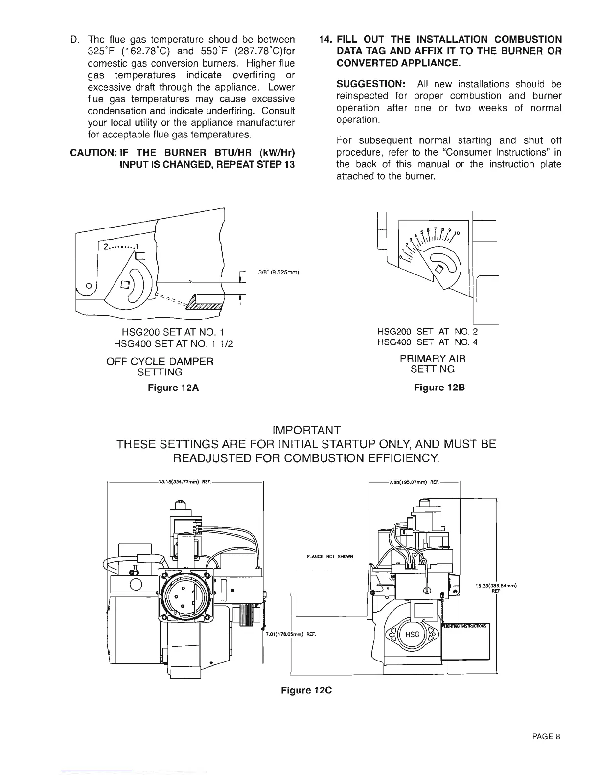
IMPORTANT
THESE
SETTINGS
ARE
FOR
INITIAL
STARTUP ONLY
AND MUST BE
READJUSTED FOR
COMBUSTION
EFFICIENCY.
,ssK
Figure 12C
PAGE
8
D.
The flue gas temperature should
be
between
325'F
(162.78'C) and
550'F
(287.78'C)for
domestic gas conversion burners. Higher flue
gas temperatures indicate overfiring or
excessive draft through the appliance. Lower
flue gas temperatures may cause excessive
condensation and indicate underfiring. Consult
your local utility or the appliance manufacturer
for acceptable flue gas temperatures.
CAUTION: IF THE BURNER BTU/HR (kWlHr)
INPUT
IS
CHANGED, REPEAT STEP 13
14. FILL OUT THE INSTALLATION COMBUSTION
DATA TAG AND AFFIX IT
TO
THE BURNER
OR
CONVERTED APPLIANCE.
SUGGESTION: All new installations should
be
reinspected for proper combustion and burner
operation after one or two weeks of normal
operation.
For subsequent normal starting and shut off
procedure, refer to the "Consumer Instructions"
in
the back of this manual or the instruction plate
attached
to
the burner.
3/8" (9.525mm)
HSG200 SET
AT
NO.1
HSG400 SET
AT
NO.1 1/2
OFF
CYCLE DAMPER
SETTING
Figure
12A
HSG200 SET
AT
NO.2
HSG400 SET
AT
NO.4
PRIMARY AIR
SETTING
Figure
12B
IMPORTANT
THESE SETTINGS ARE FOR INITIAL STARTUP
ONLY,
AND MUST BE
READJUSTED FOR COMBUSTION EFFICIENCY.
r----1J.18(JJ4.77mm)
REF
..
----j
FlANGE
NOT
SHOWN
7.01(178.05mm)
REF.
Figure
12C
7.88('95.07mm)
REF.
15.2J(J86.84mm)
REF
PAGE 8