4
www.waynepumps.com
Operating Instructions and Parts Manual
OPERATION
Never run the pump dry. Running pump without
water may cause seal damage. Fill the pump
with water before starting.
PRIMING THE PUMP
After pump installation is complete, the pump must be primed. Remove
the pipe plug in the discharge piping and ll the pump and suction pipe
with clean water. Turn power to pump on. If the pump does not pump
water in 10 minutes, turn o the pump and rell with clean water.
If the pump does not operate after repeated attempts, check the
following:
1. Vertical distance of pump to water level must not be over 25 feet.
2. Suction piping must be air tight.
3. Be sure valve(s) are open if used in discharge or suction piping.
Never run the pump with a closed or clogged
discharge. The water inside the pump could boil
and damage the pump.
MAINTENANCE
Maintain adequate ventilation for the pump motor. The motor bearings are
permanently lubricated at the factory. Additional lubrication is not required.
DRAINING FOR WINTER
Always protect pump and piping against freezing temperatures. If there is
any danger of freezing, drain the system. To drain the system:
1. Remove the pipe plug from the discharge tee.
2. Remove the 1/4” plug from the lower front face of the pump.
3. Drain all piping below the frost line.
LAWN SPRINKLER REBUILD KIT
• Disconnect all power from the pump
• Drain the pump and disconnect any plumbing.
• Remove the four bolts holding the volute to the seal plate.
• Remove the volute from the seal plate, you may need to use a
screwdriver to help separate the parts.
• Remove the square cut gasket from the seal plate and discard.
• Remove the three screws from the diuser and the diuser from
the seal plate. The intake on the diuser has an O-Ring seal and is
covered with a lubricant, remove the O-Ring and discard.
• Remove the black plastic cap from the back of the motor, exposing
the motor shaft end. (On the WLS200 you will have to remove the
plastic cover from the end of the motor.
• Using a large at blade screw driver to hold the motor shaft while
unscrewing the impeller.
• Remove the bellows portion of the shaft seal, making sure the metal
sleeve comes o as well, all you should see on the back of the
impeller is the brass colored threaded insert.
• Remove the ceramic seal and rubber boot from the seal pate, it
is easier to remove the seal by unbolting the seal plate from the
motor ange. If you remove the seal plate from the motor ange
make sure you torque the four bolts to 140 ±40 inch pounds when
reassembling it.
• Wipe down all the parts to remove any debris or loose rust.
• Reassemble the pump with new parts in reverse order.
• Push the ceramic seat of the shaft seal into the seal plate using the
cardboard ring provided to keep the ceramic face clean. You can
use a little water or dish soap to lubricate the seal pocket to make
assembly easier.
• Push the bellows side of the shaft seal over the impeller hub, you
can use a little water or dish soap to lubricate the impeller hub to
make assembly easier.
• Holding the motor shaft with a at blade screw driver, thread the
impeller onto the motor shaft, hand tighten. Lubricate the nose of
the impeller with Dow Corning III valve lubricant and sealant or other
potable water safe lubricant.
• Replace the plastic cap (or plastic cover on the WLS200) over the
motor shaft end.
• Put a new O-Ring on the diuser and lubricate the intake/O-Ring
area of the diuser with the same lubricant used on the impeller.
• Replace the diuser, rotating the diuser until the screw holes line up
with the ones in the seal plate. The diuser only goes on one way.
Torque the screws to 27±7 inch pounds.
• Slide the square cut gasket over the ange on the seal plate, make
sure not to let the gasket twist.
• Reassemble the volute to the pump being careful not to damage
the O-Ring on the diuser. Torque the four bolts to 240 ±40 inch
pounds.
• Reattach plumbing connection, reconnect the power and prime the
pump (See section on priming the pump). After reassembling the
pump, check for leaks. If a leak is detected, repair before using the
pump.
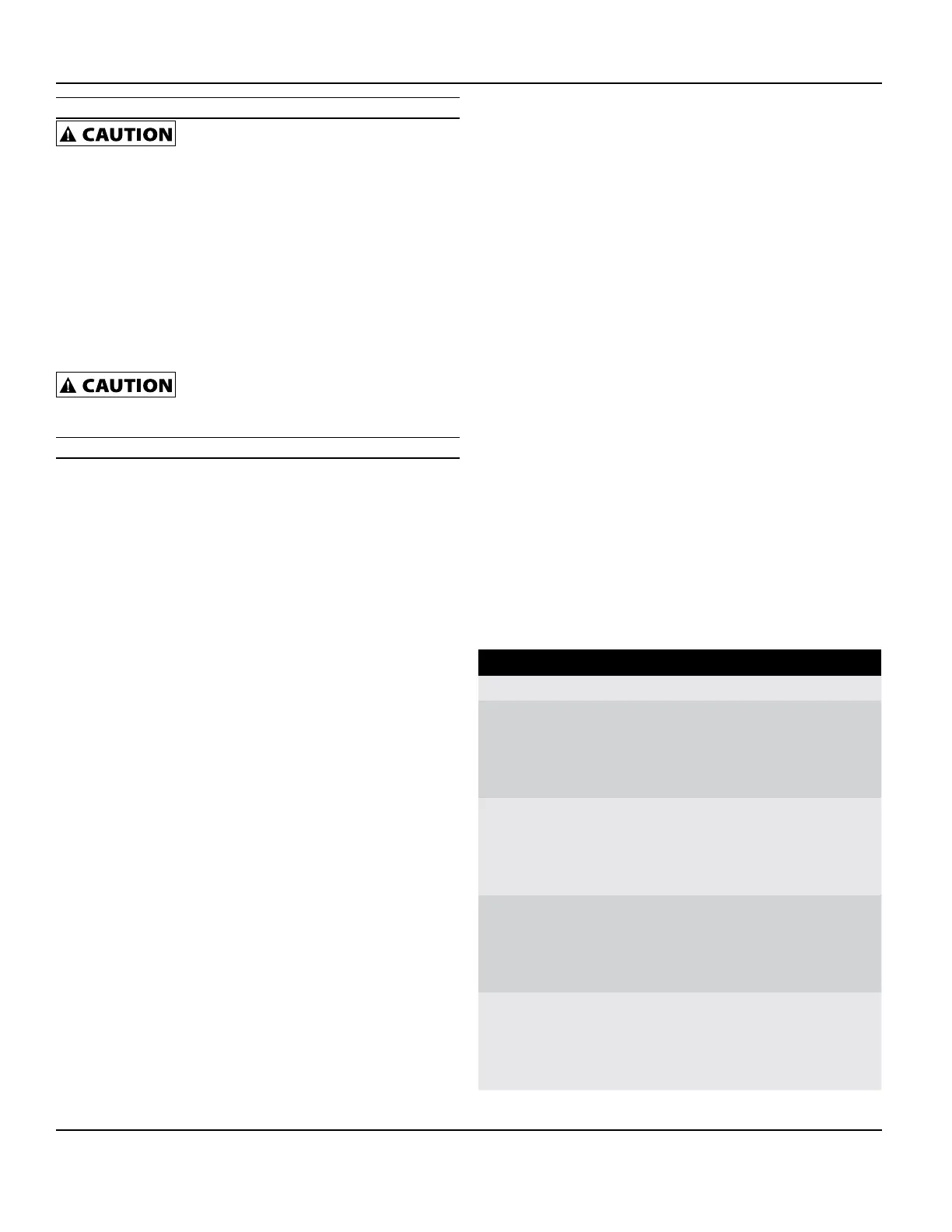
PERFORMANCE
Model PSI 5 ft. 10 ft. 15 ft. 20 ft. 25 ft.
WLS200
15 - - 5300 5150 4850
20 5300 5100 4850 4550 4300
25 4800 4500 4250 4000 3750
30
4200
3950 3750 3450 3100
WLS150
15 4350 4200 3950 3700 3500
20 3950 3700 3450 3250 3050
25 3400 3200 3000 2800 2550
30
2950
2750 2500 2150 1700
WLS100
15 3650 3450 3250 3050 2850
20 3200 3000 2850 2650 2500
25 2800 2650 2450 2300 2050
30
2450
2200 1950 1600 1150
WLS75
15 3100 2900 2750 2600 2450
20 2700 2550 2400 2200 2050
25 2350 2200 2000 1750 1450
30
1950
1700 1400 1000 500
 Loading...