WebastoAirTopInstallationGuide–AT2000STC
16
AirTop2000STCInstallationGuide2020|WebastoThermo&ComfortAustraliaPtyLtd.
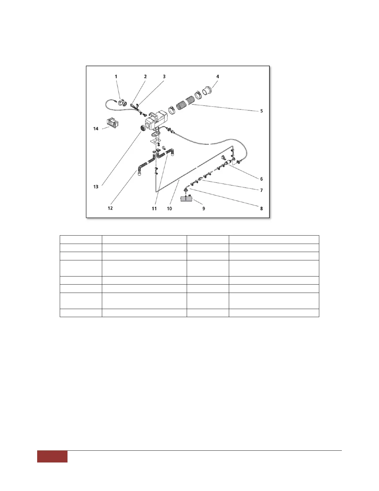
8BasicLayoutofCompl eteInstallation
9ResetProcedures
RotaryControl
(formulti‐controlpleaserefertopage24,errorcode07)
Whenthecontrollerstartstoflash,disconnectthepowersupplytotheheaterby:
1) Whilstthecontrollerisintheonposition&codeflashing,removethefuse(15A)ordisconnectpowertothe
heater
2) Turnthedialswitchtooff
3) Waitforafewminutes
4)
Re‐installthefuse
5) Restarttheheater
COMPONENT DESCRIPTION COMPONENT DESCRIPTION
1 CONTROLLER 8 FUELSTANDPIPE
2 INTERFACEVEHICLEHARNESS 9 FUELTANK
3 HEATERFUSES–F1(15A)&
F2(10A){Fig.13Pg9}
10 FUELLINE
4 HOTAIROUTLET 11 EXHAUSTPIPE
5 HOTAIROUTLETDUCT 12 COMBUSTIONAIRINTAKEPIPE
6 FUELPUMP 13 RETURN(HEATING)AIRINTAKE
GRILL
7 FUELFILTER
Fig29–BasicCompleteInstallationLayout