WebastoAirTopInstallationGuide–AT2000STC
8
AirTop2000STCInstallationGuide2020|WebastoThermo&ComfortAustraliaPtyLtd.
3 ElectricalSystem
3.1MainHarness
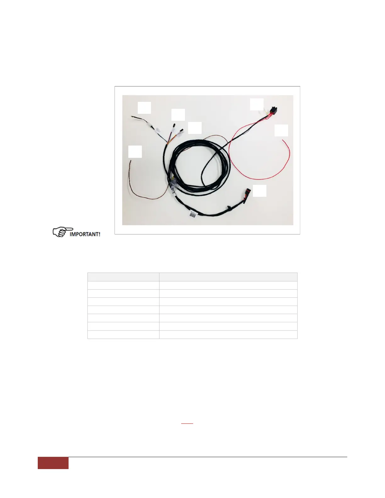
Donotcutorextendthecontrollerwiringharness.Thiswillvoidthewarranty.Ifanextensionisrequiredforthe
controlelementplug(Fig12)(X9),anextensionharnessisavailablefromWebasto.
Weonlyrecommendextendingthebatterypositive(red)andnegative(brown)wires.Correct
wiresizeof6mmtobe
usedtoavoidanycurrentorvoltagedropinthecircuit.
Ensurethatthemainplugisproperly“home”intheECU(Fig12)(3).Themainpositive(red)andnegative(brown)
hastobedirectlyconnectedtothehousebatteryandNOTviaa
masterswitchtoensurecorrectshutdowncycleof
theheater.
Number Function
1 FuseHolder
2 RedWire(BatteryPositive)
3 MainPlug
4 BrownWire(BatteryNegative)
5 620OhmResistor
6 RotaryController(Potentiometer)
7 Multi‐controldigital
Fig12
AT2000STCMainHarnessconnections
1
2
3
4
5
6
7