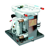
Cool Top 7
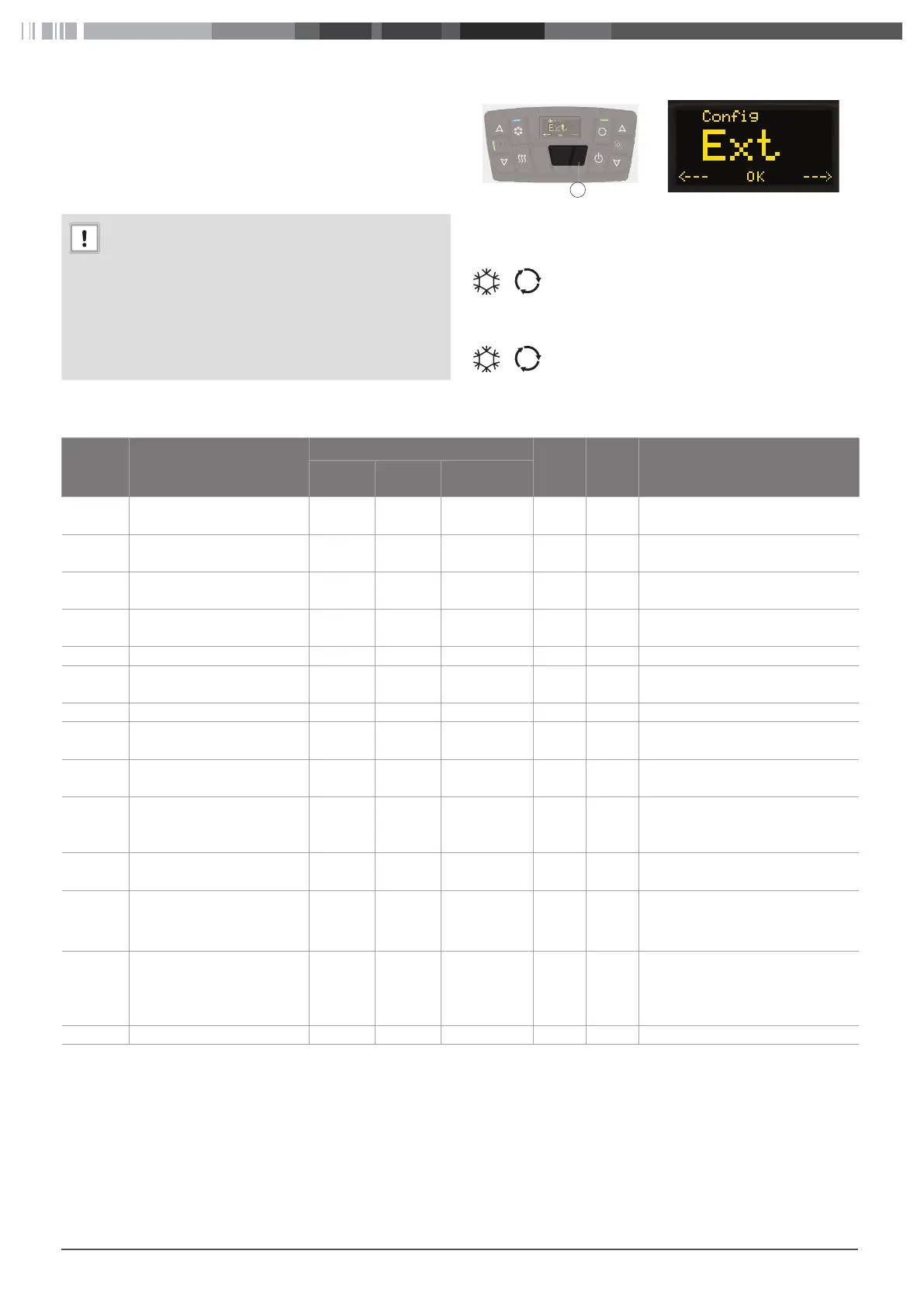
6 Configuration menu
There are several options for the Cool Top. The installer supplies a
working system with the control element configured according
the installed options.
If the system changes or a new control element need to be in-
stalled then the configuration need to be changed.
ATTENTION
If you are unfamiliar with the system then do not
change settings. Only a Webasto service workshop
can use this menu.
Result: Change of settings could lead to system malfunc-
tion.
X Contact Webasto in case you have doubts about the
configuration settings.
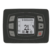
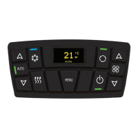
+ 8
X Press and hold buttons “MENU” and 8 for 3 sec.
–
The configuration menu opens.
X Press button “Recirculation” or “Cooling” to
switch between menu items, see Tbl. 02.
X Press button “MENU” to select menu item.
X Press button “Recirculation” or “Cooling” to ad-
just the parameter.
X Press button “MENU” to save the parameter val-
ue.
AUTO
MENU
T
8
Parameter Code Parameter Name
Default Value for Cool Top
Range R/W* Description
110/140 190/220 250/300/360
Ext External temperature sensor
(NTC3)
--- --- --- --- R Measures the external air tempera-
ture
In1 Internal temperature sensor
(NTC1)
--- --- --- --- R Measures the internal air tempera-
ture
In2 Internal auxiliary temperature
sensor (NTC4)
--- --- --- --- R Measures the Internal air tempera-
ture
Mix Supply air temperature sen-
sor (NTC2)
--- --- --- --- R Measured the supplied air tempera-
ture
Vb Vehicle battery voltage --- --- --- --- R Measures the battery voltage
Vs Sensor supply voltage (5V) --- --- --- --- R Current value measured of the sen-
sors voltage
Rel Release Software --- --- --- --- R Display 102 is version 1.02
Cnf Configuration of the operat-
ing mode
0 0 0 0-1 R/W 0 = A/C (without heating kit)
1 = HVAC (with heating kit)
Act Activation of fresh air 0 1 1 0-1 R/W 0 = Fresh air kit not present
1 = Fresh air kit present
Ntc Activation of internal auxilia-
ry temperature sensor
(NTC4)
0 0 0 0-1 R/W 0 = only internal air sensor present
1 = both internal and auxiliary air
sensors present
Bat Configuration of vehicle bat-
tery
0 1 1 0-1 R/W 0 = 12V / 1 = 24V
Blw Configuration of the blowers
mode
(ONLY for Cool Top RT-CW)
--- 0 --- 0-1 R/W 0 = 3 speeds (S1, S2 and S3)
1 = linear speed for Cool Top RT-
CW (S1, S2, S3, S4, S5 and S6)
Cmp Configuration of the com-
pressor type
--- 0 --- 0-1 R/W 0 = Short time delay compressor
(Sanden, Valeo)
1 = Long time delay compressor
(Bock)
Out Exit from menu --- --- --- --- -- Exit from configuration menu
* R = Read only / W = Write
Tbl. 02: Control element parameters