Cool Top 8
7 Installation
Find the right place in the drivers cabin where the display will fit.
ATTENTION
Wrong chosen location for cut-out
Result: Damage of wiring and or components behind
the panel.
X Check space behind panel before making the
cut-out.
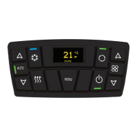
7.1 Display dimensions
Fig. 03:
112 mm / 4,41”
68,2 mm /
2,685”
138 mm / 5,43”
55 mm / 2,17”
12 mm / 0,47”
14,6 mm / 0,57”
13 mm / 0,52”
Display dimension
3
Location for control panel has been checked
X Make a cut-out of 112 mm wide and 55 mm high.
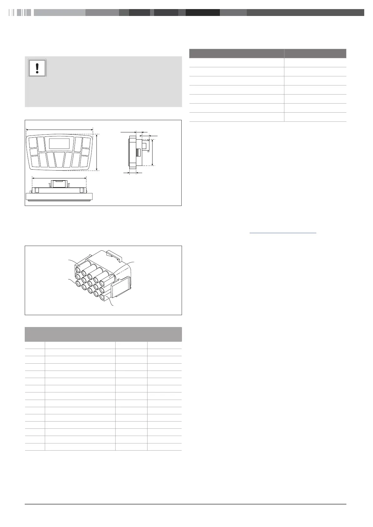
7.2 Display connector
Fig. 04:
1
3
13
15
6 pin connector
Pin Remark
Wire num-
ber
Wire colour
1 --
2 --
3 --
4 --
5 --
6 GND B-17 Black
7 +12VDC / +24VDC 027 Red
8 CAN L 012 Green
9 CAN H 013 Yellow
10 --
11 --
12 --
13 --
14 --
15 --
Tbl. 03: 6 pin connector, pin assignment
8 Technical data
Description Value
Operating voltage range [V] 12-24
Current consumption [mA] 50
Output short circuit protection Protected
Polarity reverse protection Protected
Operating temperature range [°C] -40 to +80
Temperature sensor NTC 10 kΩ @ 25°C
Protection IEC-60529 (front panel) IP54
9 Technical support and
customer service
Do you have any technical questions or problem with the device?
National phone numbers of our representatives are provided on
the following website: www.webasto.com.
9.1 CE-Declaration of Conformity
Webasto hereby declares that the control element conforms
UNECE Regulation No. 10
The complete text of the CE-declaration of conformity is available
on the download area of https://dealers.webasto.com
10 Disposal
When you eventually decommission the system, please dispose of
the individual components properly at a recycling centre
 Loading...