Page 31 of 40 Webasto Charging Systems, Inc.
Intelligent Fast-Charging System GSE Installation Guide for the DVS300/330/400 and MVS330/400
31504-76-0101
4.7.3. Wires, including shield terminations, shall be lugged using an insulated ring lug with a No. 6 hole.
4.7.4. Control Cables
4.7.4.1. Control cables run only from the server to the DVS power station (main station).
4.7.4.2. Control cables shall be constructed of two pairs of twisted wires. No shielding is required.
4.7.5. Communication Cables
Communication cables run only from power station to power station. The communication cables run from the
main station to auxiliary station 1, from auxiliary station 1 to auxiliary station 2, from auxiliary station 2 to
auxiliary station 3, and so forth.
4.7.5.1. See Table 7 for additional information.
4.7.5.2. Communication cables shall be constructed of two pairs of twisted, shielded wires.
(A cable comprising two pairs of twisted wires with a single overbraid shield also is acceptable.)
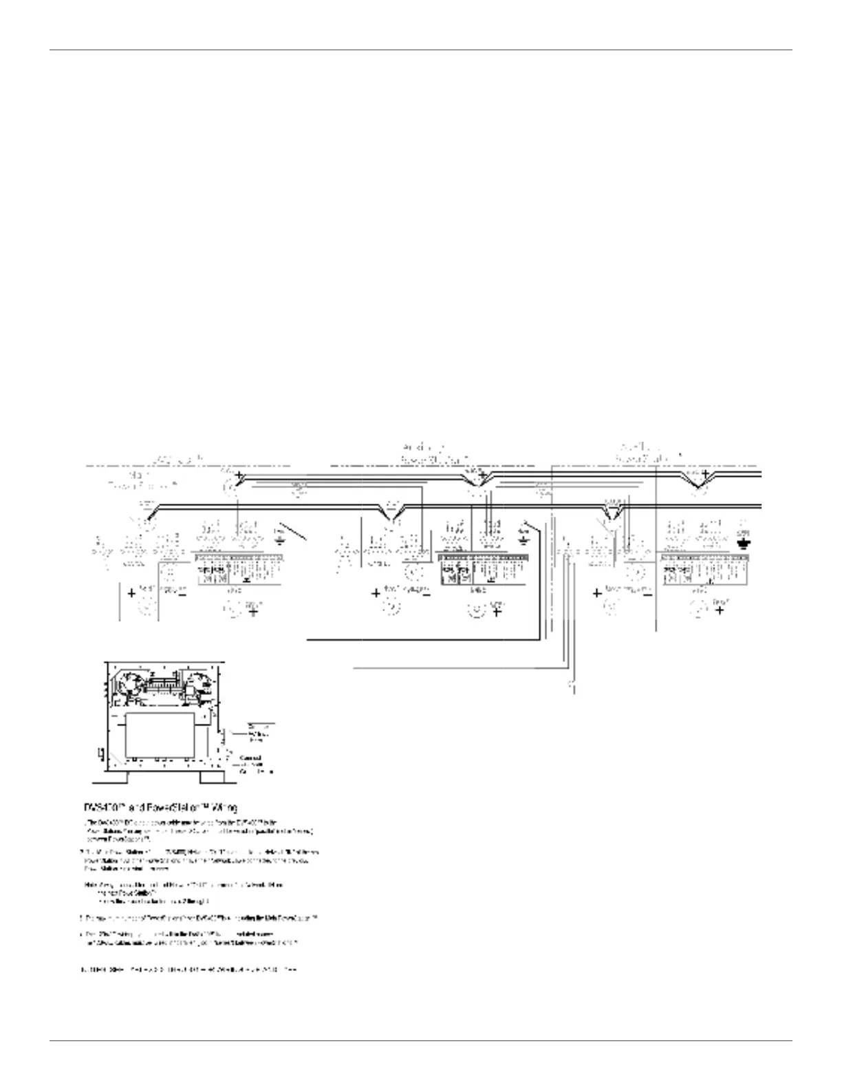
Cable shields shall be terminated together and connected and routed per Figure 13 and Figure 14.
4.7.5.3. The recommended communication cable is an Anixter wire (PN 2L-1802 POS)
or an Alpha wire (PN 45132).
4.7.5.4. Communication cable wire colors are not standardized and are subject to change.
Figure 14 MVS330/400 Wiring Diagram
 Loading...