Page 36 of 40 Webasto Charging Systems, Inc.
Intelligent Fast-Charging System GSE Installation Guide for the DVS300/330/400 and MVS330/400
31504-76-0101
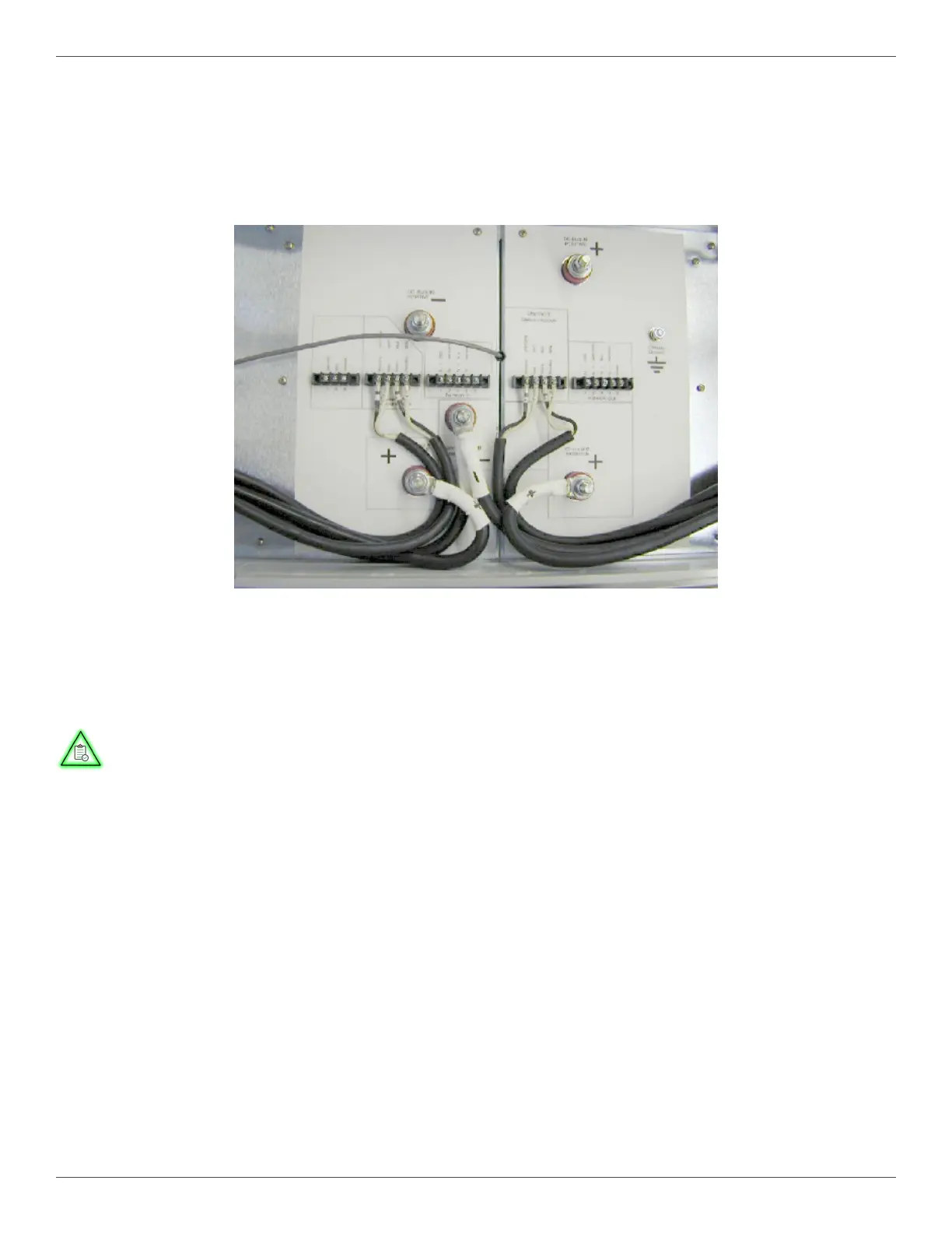
4.9.2.8. Connect the large power lugs to the terminal posts. (Figure 20).
4.9.2.9. Connect the small communication lugs to the terminal strips (Figure 20). Wires, as well as the plug
and the Burton® hub connector receptacle, are numbered to match the labeling on the
power station.
Figure 20 Electrical Connections for the Burton® Hub Connector Installation
4.9.2.10. Install the split rubber grommet (3) by separating the two halves and inserting the appropriate
power or communication cable into the slots.
Important
One half of the grommet has smaller holes, to t the smaller diameter
communication cables. The other half of the grommet has larger holes,
to t the larger diameter power cables.
NOTE
 Loading...