Page 33 of 40 Webasto Charging Systems, Inc.
Intelligent Fast-Charging System GSE Installation Guide for the DVS300/330/400 and MVS330/400
31504-76-0101
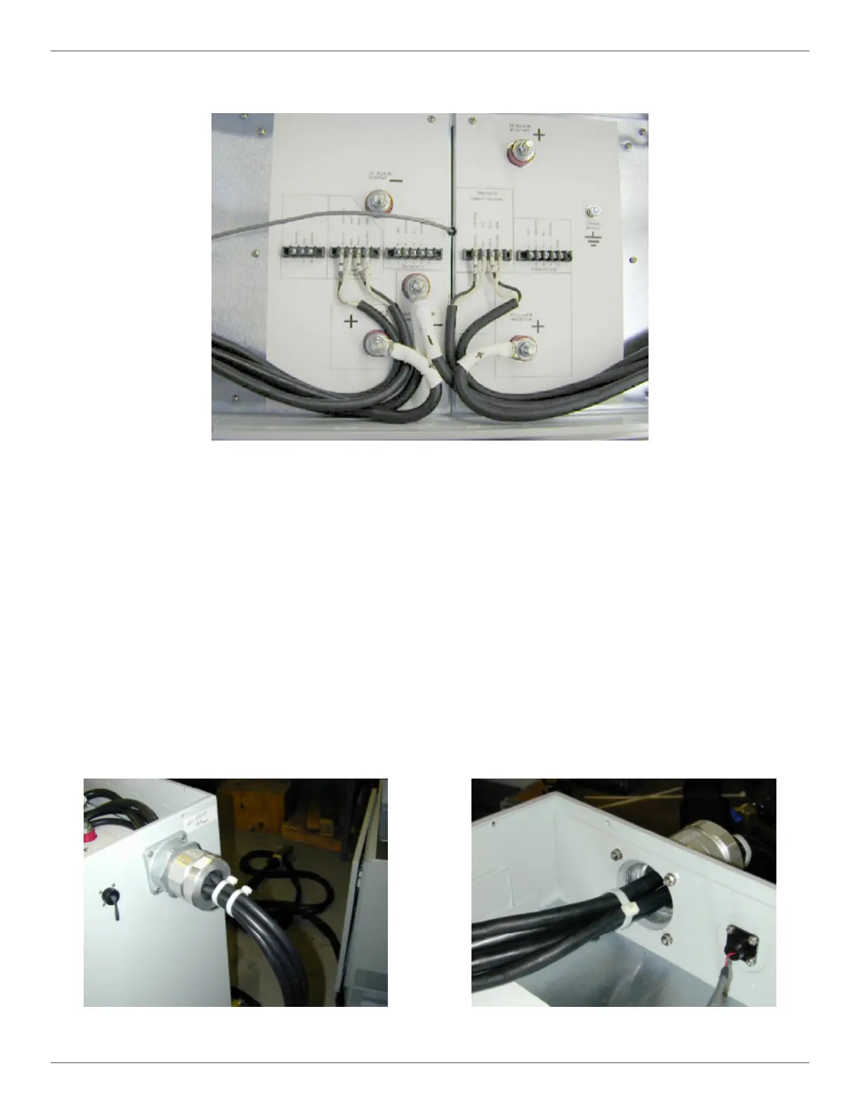
4.8.2.8. Connect the small communication lugs to the terminal strips (Figure 16). Wires, as well as the plug
and the Euro hub connector receptacle, are numbered to match the labeling on the power station.
4.8.2.9. Install the rubber grommet (3), and insert the appropriate power or communication output cable
into the slots. The grommet should be placed on the output cables as close to the feedthrough
as possible.
4.8.2.10. Push the rubber grommet (3) into the hub connector body (4).
4.8.2.11. Slide the stainless steel washer (2) and threaded cap (1) up to the tting, and tighten the assembly
until the rubber grommet (3) is tightly compressed.
4.8.2.12. Install two zip ties around the output cables at 2" and 4" from the threaded cap, outside the
power station (Figure 17). Use heavy duty zip ties that are rated for outdoor use, such as
Panduit™ PLT5H-L0.
4.8.2.13. Install one zip tie around the cables at 3" from the inside wall, inside the power station (Figure 18).
Figure 17 Power Station, Outside View Figure 18 Power Station, Inside View
4.8.2.7. Connect the large power lugs to the terminal posts (Figure 16).
Figure 16 Electrical Connections for the Euro Hub Connector Installation
 Loading...