Circuit diagrams Thermo Top C / Thermo Top E
48
12 Circuit diagrams
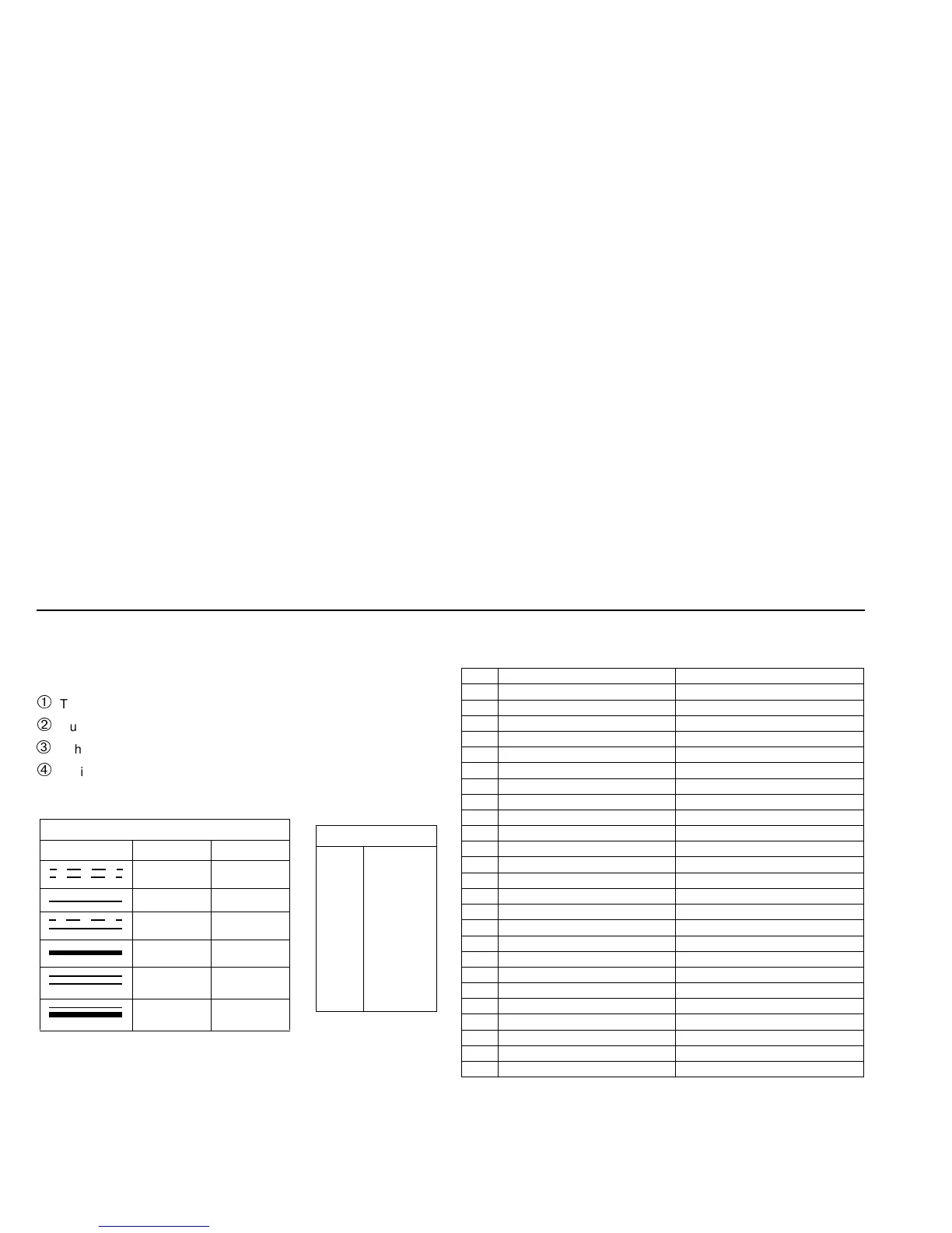
12.1. Legend for circuit diagrams:
Troubleshooting
Outside temperature
Vehicle fan fuse installed in vehicle
Optional
Cable colours
bl
br
ge
gn
gr
or
rt
sw
vi
ws
blue
brown
yellow
green
grey
orange
red
black
violet
white
Cable cross-sections
< 7.5 m 7.5 - 15 m
0.5 mm
2
0.75 mm
2
0.75 mm
2
1.5 mm
2
1.0 mm
2
1.5 mm
2
1.5 mm
2
2.5 mm
2
2.5 mm
2
4.0 mm
2
4.0 mm
2
6.0 mm
2
Item Designation Comment
A1 Heater Thermo Top E or Z/C
A2 Control unit
A3 Connecting box
B2 Temperature sensor
E Glow plug / flame monitor
F1 Fuse 20A Flat fuse DIN 72581 Part 3
F2 Fuse 1A Flat fuse DIN 72581 Part 3
F3 Fuse 25A Flat fuse DIN 72581 Part 3
H1 LED (in pos. P) Switch-on indicator
K3 Relay Vehicle fan
M1 Motor Combustion air fan
M2 Motor Circulation pump
M3 Motor Vehicle fan
P Timer, digital For programmed operation
S1 Switch for vehicle fan S1 or S2 depending on vehicle
S2 Switch for vehicle fan S1 or S2 depending on vehicle
S5 Switch Summer / winter switch
X1 Plug connection, 6-pole Water-repellent
X2 Plug connection, 2-pole Water-repellent
X3 Plug connection, 2-pole Water-repellent
X4 Plug connection, 2-pole Water-repellent
X5 Plug connection, 2-pole Water-repellent
X6 Plug connection, 2-pole Water-repellent
X9 Plug connection, 4-pole
Y1 Metering pump
 Loading...


