6 Functional Checkouts Thermo Top E and Z/C
604
6.2.6 CO
2
Setting
NOTE
The CO
2
setting is performed with the diagnosis tester
Thermo Test. For operation of diagnosis tester refer to
operating instructions.
CAUTION
For starting heater diagnostic line must be disconnected.
Connection of diagnosis tester with heater on and
operating at full load (approx. 5 min after switch on).
Change of CO
2
value in increments by pressing OK key.
For settings refer to the following table:
1. Switch on heater and allow to operate for approx.
5 min.
2. Connect screw coupling of adapter wiring harness to
diagnosis tester.
3. Connect plug (yellow wire) to diagnosis connector in
vehicle (connector with yellow wire).
4. Connect red battery terminal clamp to battery plus and
black battery terminal clamp to battery minus of
vehicle.
5. Switch on exhaust meter.
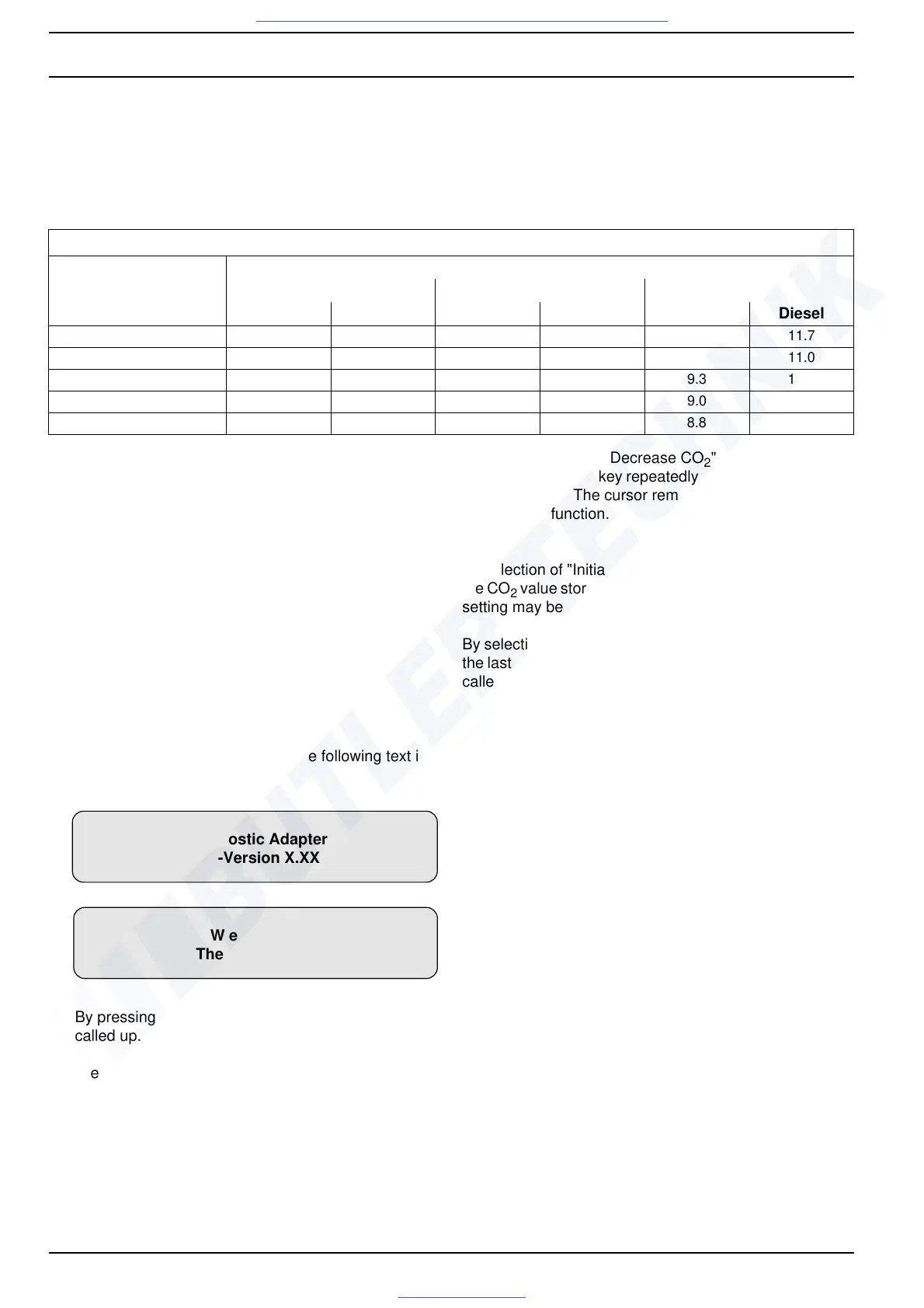
NOTE
After connection of diagnosis tester the following text is
indicated alternately:
By pressing any key the equipment select menu is
called up.
6. Press any key.
7. Select heater.
8. In main menu select “CO
2
setting”.
9. Select submenu "Decrease CO
2
" or "Increase CO
2
".
By pressing OK key repeatedly CO
2
value changes in
increments. The cursor remains positioned on the
selected function.
NOTE
By selection of "Initial value" and pressing of the OK key,
the CO
2
value stored automatically during start of the CO
2
setting may be restored.
By selection of "Store/return" and pressing of the OK key,
the last setting becomes the default and the main menu is
called up.
10. Select main menu item "Equipment selection" and
disconnect diagnosis tester from battery and from
diagnosis connection.
11. Switch off heater.
6.3 Repair Shop Level Testing
6.3.1 Components Testing
6.3.1.1 Glow Plug / Flame Sensor Resistance Check
When testing the glow plug / flame sensor with a digital
multimeter, the following readings should be obtained:
Resistance at 24 ± 6 °C: 0.245 ... 0.325
Test current: < 5 mA
Nominal contents of CO
2
in exhaust at full load operation [Vol.-%]
Geographic altitude
above sea level [m]
Air temperature [°C]
–20 0 20
Fuel Diesel Fuel Diesel Fuel Diesel
1500 10.2 11.3 10.4 11.5 10.6 11.7
1000 9.6 10.6 9.7 10.8 9.9 11.0
500 9.0 9.9 9.1 10.1 9.3 10.3
250 8.7 9.6 8.8 9.8 9.0 10.0
0 8.4 9.3 8.6 9.5 8.8 9.7
W e b a s t o
Thermosysteme
Diagnostic Adapter
SW-Version X.XX

 Loading...