7 Circuit Diagrams Thermo Top E and Z/C
704
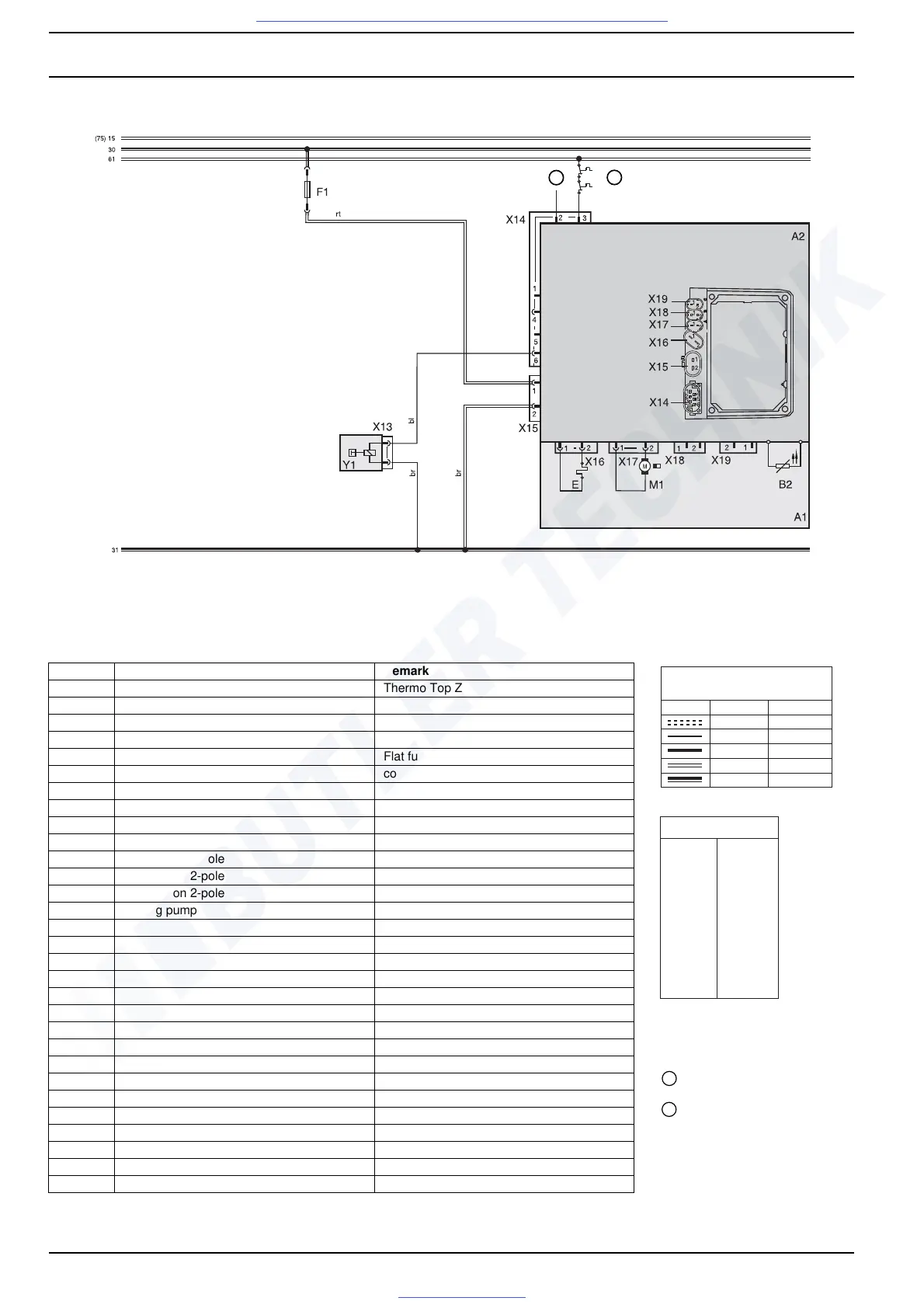
Fig. 704 Automatic Switching Circuit for Thermo Top Z, 12 V
ϑ
ϑ
ϑ
1
2
Item Nomenclature Remark
A1 Heater Thermo Top Z
A2 Control unit
B2 Temperature sensor
E Glow plug / flame sensor
F1 Fuse 20 A Flat fuse SAE J 1284
M1 Motor combustion air fan
X13 Connection 2-pole
X14 Connection 6-pole water repellant
X15 Connection 2-pole water repellant
X16 Connection 2-pole water repellant
X17 Connection 2-pole water repellant
X18 Connection 2-pole water repellant
X19 Connection 2-pole water repellant
Y1 Dosing pump
Wire Gauges
< 7.5 m 7.5 - 15 m
0,5 mm
2
0,75 mm
2
1,5 mm
2
2,5 mm
2
4,0 mm
2
0,75 mm
2
1,5 mm
2
2,5 mm
2
4,0 mm
2
6,0 mm
2
bl
br
ge
gn
gr
or
rt
sw
vi
ws
Wire Colours
blue
brown
yellow
green
grey
orange
red
black
violet
white
Legend for circuit diagrams
1
Diagnosis
2 Outside air temperature

 Loading...