Thermo Top E and Z/C 7 Circuit Diagrams
701
7 Circuit Diagrams
7.1 General
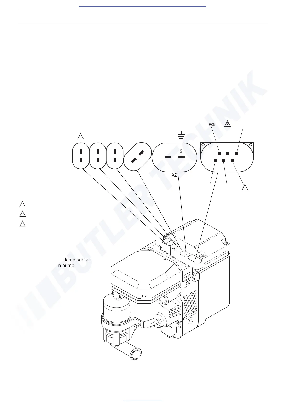
The connector pin assignment of control unit
Thermo Top E and Z/C is shown in Fig. 701.
The circuit diagrams (Fig. 702 and 703) show the
electrical circuit of the heater in combination with Timer
and Telestart T60.
The circuit diagram (Fig. 704) shows the electrical circuit
of Thermo Top Z.
Fig. 701 Control Unit Connector Pin Assignment (Thermo Top E and C)
2
Clock
12V+
1
2
UP BL GS/FW
FG
2
2
2
2
1
2
11
1
1
1
3
456
DP
Diagnosis
3
X2
X3
X4X5
X1
1
2
3
outside air temperature
summer/winter switch
not used
BL combustion air fan
DP dosing pump
FG vehicle air fan
GS/FW glow plug / flame sensor
UP circulation pump

 Loading...