Connecting to power
Note: If want to connect the LINK CAN Sensor 100 to your LINK 640, please use the Data/Power Cable sup-
plied with the LINK CAN Sensor 100.
Connect the LINK 640 to the vehicle power supply with the standard vehicle voltage (12 V/24 V). Do not
connect to a voltage converter. The three wires GND, IGN and PWR+ (supply voltage) must be connected.
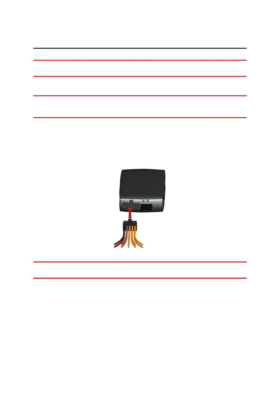
Important: Follow the order of connecting the wires as described below. First connect the wires then insert
the plug into the LINK 640. If you have inserted the plug into the LINK 640 first, you must connect the GND
wire before you connect the PWR+ wire and the IGN wire as described below.
1. Connect the GND wire (brown) to ground (clamp 31).
2. Connect the PWR+ wire (red) to the carry current (clamp 30).
The connection must be fused with max. 10 A. If not, fuse the PWR+ wire with one 4 A fast blow fuse.
3. Connect the IGN wire (black) to ignition (clamp 15).
The connection must be fused with max. 10 A. If not, fuse the IGN wire with one 4 A fast blow fuse.
4. Insert the Power/CAN plug into the power cable connector.
Note: If you need to disconnect the wires while the Power/CAN plug is plugged in the LINK 640 make sure
you disconnect the GND wire last.
11