I/O Expansion Modules
English
CFW100 | 7
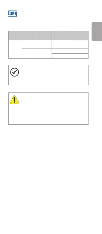
Table 2: Configuration of switch S1 to select the type of
analog input signal on the CFW100-IOAR
Input Signal
Setting of
Switch S1
Signal
Range
Parameter
Setting
AI1
Voltage
S1 = OFF
(Position I)
0 ... 10 V P233 = 0 or 2
Current
S1 = ON
(Position II)
0 ... 20 mA P233 = 0 or 2
4 ... 20 mA P233 = 1 or 3
NOTE!
The firmware version of the CFW100-IOAR
accessory can be viewed in parameter P024
of the CFW100 inverter.
ATTENTION!
For the proper operation of the CFW100
inverter with the CFW100-IOAR module,
parameters P308, P310, P311 and P312 must
be programmed with the factory settings.
For further details, refer to the programming
manual of the CFW100 V2.0X or up.