Definition of Standard IEC/EM 61800 -3: "Adjustable Speed Electrical Power Drives Systems"
Environments::
First Environment: environments that include domestic installations, as well as establishments directly
connected without intermediate transformer to a low-voltage power supply network which supplies
buildings used for domestic purposes.
Second Environment: aincludes all establishments other than those directly connected to a low-voltage
power supply network that supplies buildings used for domestic purposes.
Categories:
Categ ory C1: inverters with a voltage rating less than 1000 V and intended for use in the First Environment.
Category C2: inverters with a voltage rating less than 1000 V intended for use in the First Environment,
not provided with a plug connector or movable installations. They must be installed and commissioned by
a professional.
Category C3: inver ters with a voltage rating less than 1000 V and intended for use in the Second
Environment only (not designed for use in the First Environment).
NOTE!
A professional is a person or organization familiar with the installation and/or commissioning
of inverters, including their EMC aspects.
10.3.2 Characteristics of the RFI Filter
CFW300 inverters are installed with external filter when it is intended to reduce the disturbance conducted
from the inverter to the power line in the high frequency band (> 150). It is obser ve the maximum levels of
conducted emission of electromagnetic compatibility standards, such as EN 61800-3 and EN 55011.
For further information about the RFI filter model, refer to Table 5.
The figure below demonstrate the connection of the filter to the inverter:
Protective ground
Metal panel (when necessary)
Grounding
rod
External
input
RFI filter
PE
PE
PE
W
V
U
Signal and control wiring
Transformer
L1/ L L1
L1/ L
1...12
XC1
PE PE
L2/N L2 L2/N
CFW300
Motor
Power supply
Figure 6: Connection of the RFI f ilter - gene ral conditions
Tab l e 5 : E xternal RFI filter models for CFW300
WEG Item Name Description
13015 615 CFW300-KFA RFI filter kit CF W300 frame size A
13015 616 CFW300-KFB RFI filter kit CF W300 frame size B
Table 6: Conducted and radiated emission levels, and additional information
Inverter Model
Cond ucted Emission – Ma xim um Motor Ca ble Length Radiated Emission
Category C3 Categor y C2 Category
1 CFW300A XXPXS1XX20
(1)
27 m (1063 in) 3 m (118 in) C3
2 CFW30 0AX XPXS2X X20
(1)
27 m (1063 in) 20 m (787 in) C3
3 CFW300B10P0B2DB20 27 m (1063 in) 27 m (1063 in) C3
- The swi tching frequ ency is 5 kHz.
(1) Where there is an "X", it is assu med as a ny correspo nding value of Table 2.
10.4 ACCESSORIES
The accessories are hardware resources that can be added in the application with the CFW300.
The accessories are incorporated to the inverters in an easy and quick way by using the concept “Plug and
Play”. The accessor y must be installed or modified with the inverter de-energized. They may be ordered
separately, and are sent in their own package containing the components and manuals with detailed
instructions for their installation, operation and setting.
11 USE OF THE KEYPAD TO OPERATE THE INVERTER
Selects (toggles) display between
the parameter numbe r and its value
position/ content).
Decreases the frequency, parameter
number or parameter value.
Increases the frequency, paramete r
numbe r and parameter value.
Enables/disables the inverter via
acceleration/deceleration ramp
(start/stop, according to P229).
Resets the inverter after a fault
event.
11.1 INDICATIONS OF DISPLAY
Inverter status
Direction of rotation
Unit of measurement
(it refe rs to the va lue
of the main display)
Bar graph to monitor the variable
Main display
11. 2 OPERATING MODES OF THE HMI
Monitoring Mode
It is the initial state of the HMI after its successf ul power-up (without
the occurrence of faults, alarms or undervoltage).
Press key to go to leve l 1 of the setting m ode – select ion of setting.
Pressing any other key also switches to setting mode.
Monitoring
Setting
level 1
Setting
level 2
Setting Mode
Level 1:
This is the first level of the setting mode. T he parameter number is
shown on the main display.
Use keys and to find the desired para meter.
Press key to go to level 2 of the setting mode - change of the
parameter values.
Level 2:
The parameter value is shown on the main display.
Use keys and to set the new value in the selected parameter.
Press key to confirm th e modification (save the new value).
After confirming the modific ation, the HMI returns to level 1 of the
setting mode.
Figure 7: HMI operating modes
12 START-UP PREPARATION
DANGER!
Always disconnect the main power supply before making any connection.
1. Check if the power, grounding and control connections are correct and firm.
2. Remove all the materials left behind from the installation work from inside the inverter or the cabinet.
3. Verif y the motor connections and if its voltage and current are within the inverter rated value.
4. Mechanically uncouple the motor from the load. If the motor cannot be uncoupled, make sure that any
speed direction (for ward or reverse) will not result in personnel injur y and/or equipment damage.
5. Close the inverter or cabinet covers.
6. Measure the power supply and verify if it is within the allowed range.
7. Apply power to the input: close the input disconnecting switch.
8. Check the result of the first time power-up:
The HMI display indicates:
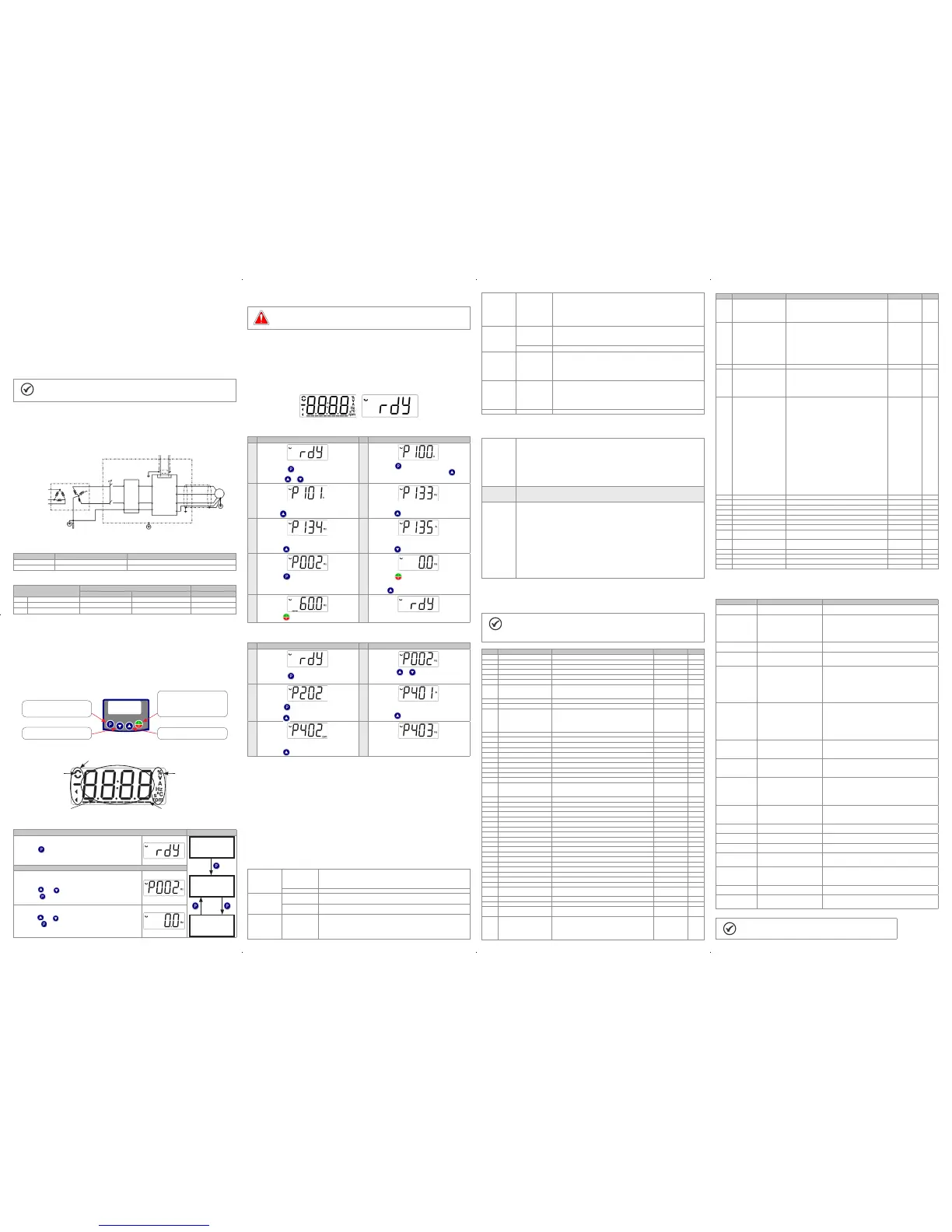
12 .1 BASIC APPLICATION
Seq Display Indication/Action Seq Display Indication/Action
1
2
Initialization mode.
Press key to enter the first level of the
parameterization mode.
Press keys or to se lect the para meter P100.
Press key if you need to change the content of
P100 – “Acceleration T ime” or p ress key for the
next parameter.
3 4
If necessary, cha nge the content of “P101 -
Deceleration Time".
Use key to select the parameter P133.
If necess ary, change the conten t of “P133 - Min imum
Sp e e d ”.
Press key for the next parameter.
5 6
If necess ary, change th e content of “P134 - Maximum
Sp e ed".
Press key for the next parameter.
If necessary, cha nge the content of “P135 - Output
Maximum Current".
Press key to select paramete r P002.
7 8
Press key to view the parameter content.
Press key that the motor will acce lerate up to
3.0 Hz (factory default setting of P133 - Minimum
Freq uency).
Press and hold it until it reaches 60.0 Hz.
9 10
Press key . The motor will decelerate to a stop.
When the motor stops, the display will indicate
“r e ady ”.
12. 2 TYPE OF CONTROL V/f (P2 02 = 0)
Seq Display Indication/Action Seq Display Indication/Action
1
2
Initialization mode.
Press key to enter the first level of the
parameterization mode.
Press keys or to se lect parameter P202.
3
4
Press key if you need to change the content of
“P202 – Type of Co ntrol” for P202 = 0 ( V/f).
Press key to select paramete r P401.
If necessary, cha nge the content of parameter “P401
– Motor Rate d Current” according to the nameplate.
Press key for the next parameter.
5
6
Se necess ário a ltere o conteúdo de "P402 - Rotação
Nominal Motor".
Press key for the next parameter.
If necessary, cha nge the content of “P403 - Motor
Rated Frequency".
13 TECHNICAL SPECIFICATIONS
PO WER DATA
Power Supply:
Tolerance: -15 % to +10 %.
Frequência: 50/60 Hz (48 Hz a 62 Hz).
Phase imbalance: ≤ 3 % of the rated phase-to-phase input voltage.
Overvoltage according to Category III (EM 61010/UL 508C).
Transient voltages according to Category III.
Maximum of 10 connections per hour (1 every 6 minutes).
Typical efficiency: ≥ 97 %.
Classification of chemically active substances: level 3C2.
Mechanical condition rating (vibration): level 3M4.
Audible noise level: < 60dB.
14 ELECTRONICS/GENERAL DATA
Tab l e 7: Electronics/general data
Control Method Types of contro l:
- V/f (Scalar)
- VV W: voltage vector control.
PWM SVM (Space Vector Modulation)
Output frequency 0 to 400 Hz, resolution of 0.1 Hz
Performance V/F control Speed regulation: 1 % of the rated speed (with slip comp ensation)
Speed variation range: 1:20
Vector control
(VVW)
Regulação de velocidade: 1 % da vel ocidade nominal
Faixa de variação de velocidade: 1:30
Inputs Analog 1 insulated input. Levels: (0 to 10) V or (0 a 20) mA or (4 to 20) mA
Linearity error ≤ 0.25 %
Impedance: 100 kΩ for voltag e input, 500 Ω for current input
Programmable functions
Maximum voltage permitted in the input: 30 Vdc
Inputs Digital 4 isolated inputs
Programmable functions:
- active high (PNP): maximum low level of 10 Vdc / minimum h igh level of 20 Vdc
- active low (NPN): maximum low level of 5 Vdc / minimum high level of 10 Vdc
Maximum input voltag e of 30 Vdc
Input current: 11 mA
Maximum input current: 20 mA
Outputs Relay 1 relay with NO/NC contact
Maximum voltage: 250 Vac
Maximum curre nt: 0.5 A
Programmable functions
Power supply 10 Vdc power supply. Max imum capacity: 50 m A
Safety Protection Overcurrent/phase-phase short circuit in the output
Under/overvoltage
Motor overload
Overtemperature in the power module (IGBTs)
Fault / exter nal alarm
Programming error
Integral keypad
(HMI))
Standard keypad 4 keys: Star t/Stop, Up arrow, Down arrow and Pro gramming
LCD Display
View/edition of all parameters
Indication accuracy:
- current: 5 % of the rated current
- speed resolution: 0.1 Hz
Enclosure IP20 Frames size s A and B
15 CONSIDERED STANDARDS
Tab l e 8 : Considered standards
Safety
standards
UL 508C - power c onver sion equipment
UL 840 - insulation coordination including clearances and creepage distances for electrical equipment
EN 61800 -5-1 - safet y requirements electrical, thermal and energy
EN 50178 - electronic equipment for use in power installations
EN 60204-1 - safety of machinery. Electrical equipment of machines. Par t 1: general requirements
Note: the final assembler of the machine is responsible for installing a safety stop device and a supply
disconnecting device
EN 60146 (IEC 146) - semiconductor converters
EN 61800 -2 - adjustabl e spee d electrical power drive systems - Part 2: ge neral requirements - rating
specifications for low voltage adjustable frequency AC power drive systems
Mechanical
standards
EN 60529 - degrees of protection provided by enclosures (IP code)
UL 50 - enclos ures fo r elec trical equipment
IEC 60721-3-3 - classification of environmental conditions
Electromagnetic
compatibility
(EMC)
standards
(*)
EN 61800 -3 - adjustable spe ed electri cal power dri ve systems - par t 3: EMC product st andard including
specific test methods
EN 55011 - limits and methods of measureme nt of radio disturbance characteristics of industrial,
scientific and medical (ISM) radio-frequency equipment
CISPR 11 - industrial, scie ntific and medical (ISM) radio-frequency equip ment - electromagnetic
disturbanc e characteristics - limits and methods of m easurement
EN 61000-4-2 - electromagnetic compatibility (EMC) - part 4: testing and measurement techniques -
section 2: electrostatic discharge immunity test
EN 61000-4-3 - electromagnetic compatibility (EMC) - part 4: testing and measurement techniques -
section 3: radiated, radio-frequency, electromagnetic field immunity test
EN 61000-4-4 - electromagnetic compatibility (EMC) - part 4: testing and measurement techniques -
section 4: electrical fast transient/burst immunity test.
EN 61000-4-5 - electromagnetic compatibility (EMC) - part 4: testing and measurement techniques -
section 5: surge immunity test.
EN 61000-4-6 - electromagnetic compatibility (EMC) - part 4: testing and measurement techniques -
section 6: immunity to conducted disturbances, induced by radio-frequency fields.
(*) Compliance with standards upon installation of RFI filter. For further details refer to consulte www.weg.net.
16 MAIN PAREMETERS
The table below contains the mains parameters of the CFW300.
NOTE!
ro = read only parameter.
V/f = parameter available in V/f mode.
cfg = configuration parameter, value can only be changed with the motor stopped.
Param. Description Adjustable Range Factory Setting Prop.
P000 Access to Parameters 0 to 99 99 1
P001 Speed Reference 0 to 9999 ro
P002 Ou tput Speed (M otor) 0 to 9999 ro
P003 Motor Current 0.0 to 40.0 A ro
P004 DC L ink Voltage (Ud ) 0 to 524 V ro
P005 Output Frequen cy (Motor) 0.0 to 400.0 Hz ro
P006 Inverter Status 0 = Read y
1 = Run
2 = Undervoltage
3 = Fault
4 = Self-Tuning
5 = Configuration
ro
P007 Output Voltage 0 to 240 V ro
P0 11 Active Current -40.0 to 40.0 A ro
P012 DI8 to DI1 Status 0 to FF (hexa)
Bit 0 = DI1
Bit 1 = DI2
Bit 2 = DI3
Bit 3 = DI4
Bit 4 = DI5
Bit 5 = DI6
Bit 6 = DI7
Bit 7 = DI8
ro
P022 FI Value in Hz 1 to 3000 Hz ro
P023 Ma in SW Version 0.00 to 99.99 ro
P030 Module Temperature 0.0 to 200.0 ºC ro
P037 Motor Overload Ixt 0.0 to 100.0 % ro
P047 CONFIG Status 0 to 999 ro
P048 Present Alarm 0 to 999 ro
P049 Present Fault 0 to 999 ro
P050 Last Faul t 0 to 999 ro
P100 Acceleration Time 0.1 to 999.9 s 5.0 s
P101 Deceleration Time 0.1 to 999.9 s 10.0 s
P120 Speed R ef. Backup 0 = Inactive
1 = Active
2 = Backu p by P121
1
P121 Referen ce via HMI 0.0 to 400.0 Hz 3.0 Hz
P124 Multispeed Ref. 1 -400.0 to 400.0 Hz 3.0 Hz
P125 Multis peed Ref. 2 -400.0 to 40 0.0 Hz 10.0 (5.0) Hz
P126 Multis peed Ref. 3 -400.0 to 40 0.0 Hz 20.0 (10.0) Hz
P127 Multispeed Ref. 4 -400.0 to 400.0 Hz 30.0 (20.0) Hz
P128 Multis peed R ef. 5 -400.0 to 40 0.0 Hz 40.0 (30.0) Hz
P129 Multis peed R ef. 6 -400.0 to 40 0.0 Hz 50.0 (40.0) Hz
P130 Multispeed Ref. 7 -400.0 to 400.0 Hz 60.0 (50.0) Hz
P131 Multispeed Ref. 8 -400.0 to 400.0 Hz 66.0 (55.0) Hz
P133 Minimum Frequency 0.0 to 40 0.0 Hz 3.0 Hz
P134 Maximum Frequency 0.0 to 400.0 Hz 66.0 (55.0) Hz
P135 Maximum Output Current 0.0 to 40.0 A 1.5 x I
nom
P136 Manual Torque Boost 0.0 to 30.0 % 0.0 % V/f
P137 Automatic Torque Boost 0.0 to 30.0 % 0.0 % V/ f
P138 Slip Compensation -10.0 to 10.0 % 0.0 % V/f
P139 Output Current Filter 0.000 to 9.999 s 0.005 s
P142 Maximum Output Voltage 0.0 to 100.0 % 100.0 % c fg, V/f
P143 Intermediate Output Voltage 0.0 to 100.0 % 50.0 % cfg, V/f
P145 Field Weakening Start
Frequency
0.0 to 400.0 Hz 60.0 (50.0) Hz cfg, V/ f
P146 Intermediate Frequency 0.0 to 400.0 Hz 30.0 (25.0) Hz cfg, V/f
P156 Overload Current 0.1 to 2.0 x I
nom
1.2 x I
nom
P202 Type of C ontrol 0 = V/f
1 = V/f Qua dratic
2 to 4 = Not Used
5 = V V W
0 cfg
P204 Load/Save Parameters 0 to 4 = Not Used
5 = Load 60 Hz
6 = Load 50 Hz
7 = Load Use r 1
8 = Not Used
9 = Save User 1
10 = Not Used
11 = Load Default S oftPLC
12 to 13 = Reserved
0 cfg
Param. Description Adjustable Range Factory Setting Prop.
P220 LOC/REM Selection Source 0 = Always Local
1 = Always Remote
2 to 3 = Not Used
4 = DIx
5 = Serial/US B (LOC)
6 = Serial/US B (REM)
7 to 8 = Not Used
9 = CO/DN/ DP (LOC)
10 = CO/DN/DP (REM)
11 = SoftPLC
0 cfg
P221 LOC Reference Sel 0 = HMI Keys
1 = AI1
2 = AI2
3 = Not Used
4 = FI
5 = AI1 + AI 2 > 0
6 = AI1 + AI2
7 = E.P.
8 = Multispeed
9 = Serial/USB
10 = Not Used
11 = CO/DN/DP
12 = SoftPLC
13 = Not Used
14 = AI1 > 0
15 = AI2 > 0
16 = Not Used
17 = FI > 0
0 cfg
P222 REM Re feren ce Sel. See Options in P221 3 cfg
P223 LOC Rotation Sel. 0 = For ward
1 = Reverse
2 to 3 = Not Used
4 = DIx
5 = Serial/US B (FWD)
6 = Serial/US B (REV)
7 to 8 = Not Used
9 = CO/DN/ DP (FWD)
10 = CO/DN/DP (REV )
11 = Not Used
12 = SoftPLC
0 cfg
P263 DI1 Input Function 0 = Not Used
1 = Run/Stop
2 = General Enable
3 = Not Used
4 = Forwa rd
5 = Reverse
6 = Star t
7 = Stop
8 = Direction of Rotation
9 = LOC/REM
10 = JOG
11 = Increase E.P.
12 = Decelerate E.P.
13 = Multispeed
14 = 2
nd
Ramp
15 to 17 = Not Used
18 = No Ext. Alarm
19 = No Ext. Fault
20 = Reset
21 to 23 = Not Used
24 = Disab. Flying Start
25 = Regul. DC Link
26 = Lock Pro g.
27 to 31 = Not Used
32 = 2
nd
Ramp Multispeed
33 = 2
nd
Ramp E.P. Ac.
34 = 2
nd
Ramp E.P. De.
35 = 2
nd
Ramp F WD Run
36 = 2
nd
Ramp Rev Run
37 = Turn ON / Ac. E.P.
38 = De. E.P. / Turn OFF
39 = Stop
40 = Safet y Switc h
41 = Function 1 Application
42 = Function 2 Application
43 = Function 3 Application
44 = Function 4 Application
45 = Function 5 Application
46 = Function 6 Application
47 = Function 7 Application
48 = Function 8 Application
1 cfg
P264 DI2 Input Function See Options in P263 8 cfg
P265 DI3 Input Function See O ptions in P263 0 cfg
P266 DI4 Input Function See Options in P263 0 cfg
P267 DI5 Input Function See Options in P263 0 cfg
P268 DI6 Input Function See Options in P263 0 cfg
P269 DI7 Input Function See Options in P263 0 cfg
P270 DI8 Input Function See Opti ons in P263 0 cfg
P295 Inv. Rated Current 1.6 to 15.2 A According inverter
model
ro
P296 Line Rated Voltage 0 = Reserved
1 = 110 / 127 Vac
2 = 200 / 240 Vac or
310 Vd c
According inverter
model
ro
P297 Switching Frequency 2.5 to 15.0 kHz 5.0 kHz cfg
P401 Motor Rated Current 0.0 to 40.0 A 1.0 x I
nom
cfg
P402 Motor Rated Sp eed 0 to 9999 r pm 1720 (1310) rpm cfg
P403 Moto r Rated Fre quency 0 to 400 Hz 60 (50) Hz cfg
17 FAULTS AND ALARMS
Most common faults and alarms
Fault / A lar m Description Possible Causes
A046
Motor Overload
Motor overload alarm Settings of P156 is too low for the used motor
Overload on the motor s haft
A050
Power Module
Overtemperature
Overtemperature alarm from the power
module temperature sensor (NTC)
High tempe rature at IGBTs: P030 > 90 °C (> 194 °F) (Fra me size A)
and P03 0 > 116 °C (> 240.8 °F) (Frame size B)
High ambie nt temperature aroun d the inve rter (> 50 °C (> 122 °F))
and high output current
Blocked or defecti ve fan
Heatsink is too dirty, preventing the a ir flow
A090
External Alarm
Exte rnal alarm via DIx (option “no
external ala rm” in P26 3 to P270)
Wiring on DI1 to DI8 inputs are ope n or have po or contact
A700
Remote HMI
Communication
No communication with remote HMI,
but here is freq uency comma nd or
reference for this source
Check if the c ommunicati on inter face with the H MI is pro perly
confi gured i n parameter P312
HMI cable disconnected
F021
Undervoltage on the
DC Link
Undervoltage fault on the intermediate
circuit
Wrong voltag e supply; che ck if the data on t he inverter l abel compl y
with the p ower supply an d parameter P29 6
Supply voltage too low, producing voltage on the DC link b elow
the minimum val ue (in P004):
Ud < 250 Vdc in 110 / 127 Vac (P296 = 1) or Ud < 200 Vdc in
200 / 240 Vac (P296 = 2)
Phase fault in the inp ut
Fault in the pre -cha rge circuit
F022
Overvoltage on the DC
Link
Overvoltage fault on the intermediate
circuit
Wrong voltag e supply; che ck if the data on t he inverter l abel compl y
with the p ower supply an d parameter P29 6
Supply voltage is too high, p roduc ing voltage on the DC link above
the maximum value (in P004):
Ud > 460 Vdc in 110 / 127 Vac (P296 = 1) or Ud > 410 Vdc in
200 / 240 Vac (P296 = 2).
Load inertia is too high or de celeration r amp is too fast
P151 setting is too hig h
F031
Fault in Communication
with IOs Expansion
Accessory
Main control cannot establish the
communication link with the IOs
expansion accessory
Accessory damaged
Poor connection of the accessory
Problem in th e identification of th e acce ssor y; refer to P027
F032
Fault in Communication
with IOs Communication
Accessory
Main control cannot establish
the communication link with the
communication acccessory
Accessory damaged
Poor connection of the accessory
Problem in th e identification of th e acce ssor y; refer to P028
F051
IG B Ts
Overtemperatures
Overtemperature fault measured
on the temperature sensor of the
power pack
High tempe rature at IGBTs: P030 > 100 °C (> 212 °F) ( Frame size A)
e P030 > 126 °C (> 258.8 °F ) (Frame size B)
High ambie nt temperature around the inverter (>50 °C (>122 °F))
and high output current
Blocked or defecti ve fan
Heatsink is too dirty, preventing the a ir flow
F070
Overcurrent/
Shortcircuit
Overcurrent or short-circuit on the
output, DC link or braki ng resistor
Short-circuit between two motor phases
IGBTs module in short-circuit or damaged
Start with too shor t acc eleration ra mp
Start with motor spinning without the Flying Start f uncti on
F072
Motor Overload
Motor overload fault (60 s i n 1.5 x Inom) P156 setting is too low in rela tion to the motor ope rating curre nt
Overload on the motor s haft
F080
CPU Fault (Watchdog)
Fault related to the supervision
algor ithm of th e inver ter main CPU
Electric noise
Inverter firmware fault
F081
End of Use r’s Memor y
Fault of end of memory to save user’s
parameter table
Attempt to save (P 204 = 9) more than 32 pa ramete rs (with value s
different from the factory default) on the User parameter table
F082
Fault in the Copy
Function (MMF)
Fault in the copy of parameters Attempt to copy the paramete rs from the flash memo ry module to
the inverter with dif ferent soft ware ve rsions
F084
Auto-diagnosis Fault
Fault related to the automatic
identification algorithm of the inverter
hardware
Poor contact in the connection between the main control anthe
power pack
Hardware not compatible with the firmware version
Defect on the i nternal circuits of the inver ter
F091
External Fault
Exte rnal fault via DIx (“no extern al
fault ” in P263 to P270)
Wiring on DI1 to DI8 inputs are ope n or have po or contact
F701
Remote HMI
Communication Fault
No communication with the remote
HMI; however, there is command or
frequ ency reference for thi s source
Check that the HMI communication interface is properly configured
in parameter P312
HMI cable disconnected
NOTE!
For further information, refer www.weg.net.
Document: 10003587596 / 00
 Loading...


