10
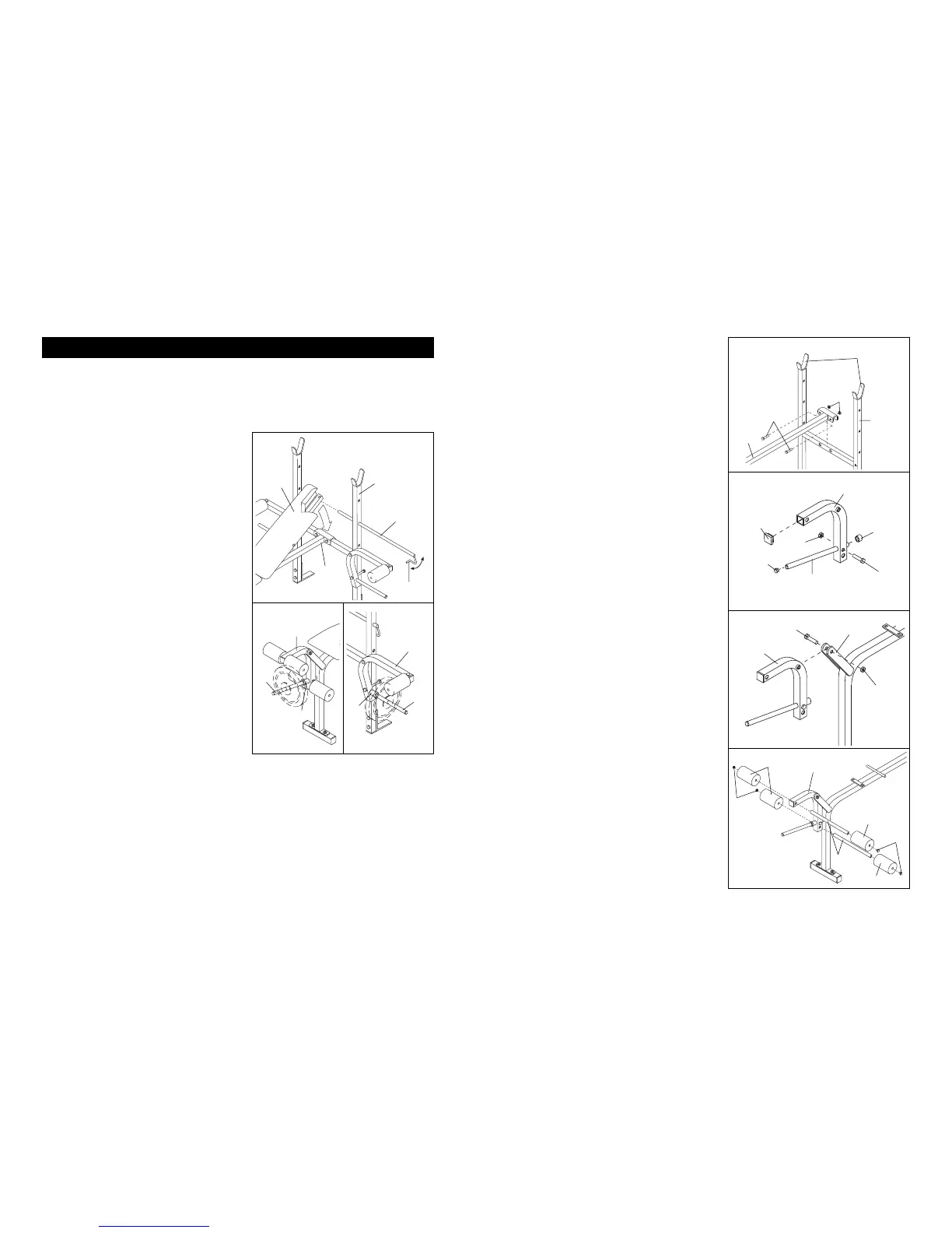
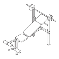
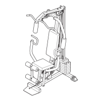
ADJUSTING THE BACKREST
The Backrest (6) can be used in either a level position
or an inclined position. To use the Backrest in a level
position, remove the Support Rod (7) and lay the
Backrest on the Main Frame (2).
To use the Backrest (6) in an inclined position, first lift
the Backrest. Insert the Support Rod (7) through one of
the three sets of holes in the “H”-Frame (1). Rotate the
Support Rod to the locked position, with the “J”-Hook
around one side of the “H”-Frame. Lay the Backrest on
the Support Rod.
ATTACHING WEIGHTS TO THE WEIGHT BENCH
To use the Leg Lever (4), first slide a Weight Stop (38)
onto the Weight Tube (34). Next, slide the desired
weights (not included) onto the Weight Tube. WARN-
ING: Do not place more than 50 pounds on the Leg
Lever.
To use the Fly Arms (22), first slide a Weight Stop (38)
onto the Fly Arm Tubes (29). Next, slide the desired
weights (not included) onto the Fly Arm Tubes. WARN-
ING: Do not place more than 30 pounds on each
Arm.
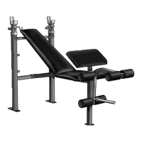
The steps below explain how the weight bench can be adjusted. See EXERCISE GUIDELINES on page 11 for
important exercise information and refer to the accompanying exercise poster to see the correct form for each
exercise.
Inspect and tighten all parts each time you use the weight bench. Replace any worn parts immediately. The
weight bench can be cleaned with a damp cloth and a mild, non-abrasive detergent. Do not use solvents.
7
“J”-Hook
6
2
1
22
34
38
4
29
38
7
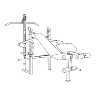
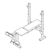
3. Be sure that the “H”-Frame (1) is oriented as
shown. The high side of the weight rests must be
on the side indicated. Attach the Main Frame (2) to
the “H”-Frame (1) with two 5/16” x 2 1/4” Bolts (16)
and two 5/16” Nylon Locknuts (19).
4. Attach the Weight Tube (34) to the Leg Lever (4)
with a 5/16” x 2” Bolt (15) and a 5/16” Nylon
Locknut (19).
Press a 1” Round Inner Cap (24) into the indicated
end of the Weight Tube (34). Press the 1” Angled
Round Cap (31) onto the Weight Tube. Press a 1
1/2” Square Inner Cap (30) into the indicated end of
the Leg Lever (4).
5. Lubricate the 3/8” x 2 1/4” Bolt (14). Attach the Leg
Lever (4) to the Main Frame (2) with the 3/8” x 2 1/4”
Bolt and a 3/8” Jam Nut (18). Do not overtighten
the Jam Nut. The Leg Lever must be able to
pivot freely.
6. Tap two 3/4” Round Inner Caps (26) into each Pad
Tube (10). Insert the Pad Tubes through the holes
in the Leg Lever (4). Slide two Foam Pads (23)
onto each Pad Tube.
6
3
4
5
30
4
31
15
34
24
19
1
19
16
2
4
2
18
Lubricate—14
4
26
High Side of
Weight Rests
23
23
10
26
23
Adjusting the Weight Bench